Fastener Design Manual
Cleaned markdown reader for the NASA fastener design handbook, published for public reference and engineering lookup use.
Errata
ERRATA
NASA Reference Publication 1228
Fastener Design Manual
Richard T. Barrett
March 1990
The manual describes various platings that may be used for corrosion control including cadmium and zinc plating. It does not mention outgassing problems caused by the relatively high vapor pressure of these metals. The fastener manual was intended primarily for aeronautical applications, where outgassing is typically not a concern.
Issued June 17, 2008
Summary
This manual was written for design engineers to enable them to choose appropriate fasteners for their designs. Subject matter includes fastener material selection, platings, lubricants, corrosion, locking methods, washers, inserts, thread types and classes, fatigue loading, and fastener torque. A section on design criteria covers the derivation of torque formulas, loads on a fastener group, combining simultaneous shear and tension loads, pullout load for tapped holes, grip length, head styles, and fastener strengths. The second half of this manual presents general guidelines and selection criteria for rivets and lockbolts.
Introduction
To the casual observer the selection of bolts, nuts, and rivets for a design should be a simple task. In reality it is a difficult task, requiring careful consideration of temperature, corrosion, vibration, fatigue, initial preload, and many other factors. The intent of this manual is to present enough data on bolt and rivet materials, finishes, torques, and thread lubricants to enable a designer to make a sensible selection for a particular design. Locknuts, washers, locking methods, inserts, rivets, and tapped holes are also covered.
General Design Information
Fastener Materials
Bolts can be made from many materials, but most bolts are made of carbon steel, alloy steel, or stainless steel. Stainless steels include both iron- and nickel-based chromium alloys. Titanium and aluminum bolts have limited usage, primarily in the aerospace industry. Carbon steel is the cheapest and most common bolt material. Most hardware stores sell carbon steel bolts, which are usually zinc plated to resist corrosion. The typical ultimate strength of this bolt material is 55 ksi. An alloy steel is a high-strength carbon steel that can be heat treated up to 300 ksi. However, it is not corrosion resistant and must therefore have some type of coating to protect it from corrosion. Aerospace alloy steel fasteners are usually cadmium plated for corrosion protection. Bolts of stainless steel (CRES) are available in a variety of alloys with ultimate strengths from 70 to 220 ksi. The major advantage of using CRES is that it normally requires no protective coating and has a wider service temperature range than plain carbon or alloy steels. A partial listing of bolt materials is given in table I. The following precautions are to be noted:
- The bolt plating material is usually the limiting factor on maximum service temperature.
- Carbon steel and alloy steel are unsatisfactory (become brittle) at temperatures below -65 °F.
- Hydrogen embrittlement is a problem with most common methods of plating, unless special procedures are used. (This subject is covered more fully in the corrosion section.)
- Series 400 CRES contains only 12 percent chromium and thus will corrode in some environments.
- The contact of dissimilar materials can create galvanic corrosion, which can become a major problem. (Galvanic corrosion is covered in a subsequent section of this manual.)
Platings and Coatings
Most plating processes are electrolytic and generate hydrogen. Thus, most plating processes require baking after plating at a temperature well below the decomposition temperature of the plating material to prevent hydrogen embrittlement. However, heating the plating to its decomposition temperature can generate free hydrogen again. Thus, exceeding the safe operating temperature of the plating can cause premature fastener failure due to hydrogen embrittlement as well as loss of corrosion protection. (A summary of platings and coatings is given in table II.)
Cadmium Plating
The most common aerospace fastener plating material is cadmium. Plating is done by electrodeposition and is easy to accomplish. However, cadmium-plated parts must be baked at 375 °F for 23 hours, within 2 hours after plating, to prevent hydrogen embrittlement. Since cadmium melts at 600 °F, its useful service temperature limit is 450 °F.
TABLE I.—SUMMARY OF FASTENER MATERIALS
| Material | Surface treatment | Useful design temperature limit, °F | Ultimate tensile strength at room temperature, ksi | Comments |
|---|---|---|---|---|
| Carbon steel | Zinc plate | -65 to 250 | 55 and up | — |
| Alloy steels | Cadmium plate, nickel plate, zinc plate, or chromium plate | -65 to limiting temperature of plating | Up to 300 | Some can be used at 900 °F |
| A-286 stainless | Passivated per MIL-S-5002 | -423 to 1200 | Up to 220 | — |
| 17-4PH stainless | None | -300 to 600 | Up to 220 | — |
| 17-7PH stainless | Passivated | -200 to 600 | Up to 220 | — |
| 300 series stainless | Furnace oxidized | -423 to 800 | 70 to 140 | Oxidation reduces galling |
| 410, 416, and 430 stainless | Passivated | -250 to 1200 | Up to 180 | 47 ksi at 1200 °F; will corrode slightly |
| U-212 stainless | Cleaned and passivated per MIL-S-5002 | 1200 | 185 | 140 ksi at 1200 °F |
| Inconel 718 stainless | Passivated per QQ-P-35 or cadmium plated | -423 to 900 or cadmium plate limit | Up to 220 | — |
| Inconel X-750 stainless | None | -320 to 1200 | Up to 180 | 136 ksi at 1200 °F |
| Waspalloy stainless | None | -423 to 1600 | 150 | — |
| Titanium | None | -350 to 500 | Up to 160 | — |
Zinc Plating
Zinc is also a common type of plating. The hot-dip method of zinc plating is known commercially as galvanizing. Zinc can also be electrodeposited. Because zinc plating has a dull finish, it is less pleasing in appearance than cadmium. However, zinc is a sacrificial material. It will migrate to uncoated areas that have had their plating scratched off, thus continuing to provide corrosion resistance. Zinc may also be applied cold as a zinc-rich paint. Zinc melts at 785 °F but has a useful service temperature limit of 250 °F. (Its corrosion-inhibiting qualities degrade above 140 °F.)
Phosphate Coatings
Steel or iron is phosphate coated by treating the material surface with a diluted solution of phosphoric acid, usually by submerging the part in a proprietary bath. The chemical reaction forms a mildly protective layer of crystalline phosphate. The three principal types of phosphate coatings are zinc, iron, and manganese. Phosphate-coated parts can be readily painted, or they can be dipped in oil or wax to improve their corrosion resistance. Fasteners are usually phosphated with either zinc or manganese. Hydrogen embrittlement seldom is present in phosphated parts. Phosphate coatings start deteriorating at 225 °F (for heavy zinc) to 400 °F (for iron phosphate).
Nickel Plating
Nickel plating, with or without a copper strike (thin plating), is one of the oldest methods of preventing corrosion and improving the appearance of steel and brass. Nickel plating will tarnish unless it is followed by chromium plating. Nickel plating is a more expensive process than cadmium or zinc plating and also must be baked the same as cadmium after plating to prevent hydrogen embrittlement. Nickel plating is good to an operating temperature of 1100 °F, but is still not frequently used for plating fasteners because of its cost.
TABLE II.—SUMMARY OF PLATINGS AND COATINGS
| Type of coating | Useful design temperature limit, °F | Remarks |
|---|---|---|
| Cadmium | 450 | Most common for aerospace fasteners |
| Zinc | 140 to 250 | Self-healing and cheaper than cadmium |
| Phosphates: Manganese | 225 | Mildly corrosion resistant but main use is for surface treatment prior to painting. Another use is with oil or wax for deterring corrosion. |
| Phosphates: Zinc | 225 to 375 | Mildly corrosion resistant but main use is for surface treatment prior to painting. Another use is with oil or wax for deterring corrosion. |
| Phosphates: Iron | 400 | Mildly corrosion resistant but main use is for surface treatment prior to painting. Another use is with oil or wax for deterring corrosion. |
| Chromium | 800 to 1200 | Too expensive for most applications other than decorative |
| Silver | 1600 | Most expensive coating |
| Black oxide (and oil) | 300a | Ineffective in corrosion prevention |
| Preoxidation (CRES) fasteners only | 1200 | Prevents freeze-up of CRES threads due to oxidation after installation |
| Nickel | 1100 | More expensive than cadmium or zinc |
| SermaGard and Sermatel W | 450 to 1000 | Dispersed aluminum particles with chromates in a water-based ceramic base coat |
| Stalgard | 475 | Proprietary organic and/or organic-inorganic compound used for corrosion resistance and lubrication (in some cases) |
| Diffused nickel-cadmium | 900 | Expensive and requires close control to avoid hydrogen damage |
a Oil boiling point.
Ion-Vapor-Deposited Aluminum Plating
Ion-vapor-deposited aluminum plating was developed by McDonnell-Douglas for coating aircraft parts. It has some advantages over cadmium plating:
- It creates no hydrogen embrittlement.
- It insulates against galvanic corrosion of dissimilar materials.
- The coating is acceptable up to 925 °F.
- It can also be used for coating titanium and aluminums.
- No toxic byproducts·are formed by the process. It also has some disadvantages:
- Because the process must be done in a specially designed vacuum chamber, it is quite expensive.
- Cadmium will outperform ion-vapor-deposited aluminum in a salt-spray test.
Chromium Plating
Chromium plating is commonly used for automotive and appliance decorative applications, but it is not common for fasteners. Chromium-plated fasteners cost approximately as much as stainless steel fasteners. Good chromium plating requires both copper and nickel plating prior to chromium plating. Chromium plating also has hydrogen embrittlement problems. However, it is acceptable for maximum operating temperatures of 800 to 1200 °F.
Sermatel W and SermaGard
Sermatel W and SermaGard are proprietary coatings 1 consisting of aluminum particles in an inorganic binder with chromates added to inhibit corrosion. The coating material is covered by AMS3126A, and the procedure for applying it by AMS2506. The coating is sprayed or dipped on the part and cured at 650 °F. (sps Technologies2 has tested Sermatel W-coated fasteners at 900 °F without degradation.) This coating process prevents both hydrogen embrittlement and stress corrosion, since the fastener is completely coated. Sermatel is about as effective as cadmium plating in resisting corrosion but costs about 15 percent more than cadmium. Fasteners are not presently available "off the shelf' with Sermatel W or SermaGard coating, but the company will do small orders for fasteners or mechanical parts. These coatings will take up to 15 disassemblies in a threaded area without serious coating degradation.
Stalgard
Stalgard is a proprietary coating3 process consisting of organic coatings, inorganic-organic coatings, or both for corrosion resistance. According to Stalgard test data their coatings are superior to either cadmium or zinc plating in salt-spray and weathering tests. Stalgard coatings also provide galvanic corrosion protection. However, the maximum operating temperature of these organic coatings is 475 °F.
Diffused Nickel-Cadmium Plating
This process was developed by the aerospace companies for a higher temperature cadmium coating. A 0.0004-in.-thick nickel coating is plated on the substrate, followed by a 0.0002-in.-thick. cadmium plate (per AMS2416). The part is then baked for 1 hour at 645 °F. The resulting coating can withstand 1000 °F. However, the nickel plate must completely cover the part at all times to avoid cadmium damage to the part. This process is expensive and requires close control.
1 Sermatech International, Inc., Limerick, Pennsylvania.
2 Jenkintown, Pennsylvania.
3 Elco Industries, Rockford, Illinois.
Silver Plating
Silver plating is cost prohibitive for most fastener applications. The big exception is in the aerospace industry, where silver-plated nuts are used on stainless steel bolts. The silver serves both as a corrosion deterrent and a dry lubricant. Silver plating can be used to 1600 °F, and thus it is a good high-temperature lubricant. Since silver tarnishes from normal atmospheric exposure, the silver-plated nuts are commonly coated with clear wax to prevent tarnishing. Wax is a good room-temperature lubricant. Therefore, the normal ''dry torque'' values of the torque tables should be reduced by 50 percent to allow for this lubricant.
Passivation and Preoxidation
Stainless steel fasteners will create galvanic corrosion or oxidation in a joint unless they are passivated or preoxidized prior to assembly (ref. 1). Passivation is the formation of a protective oxide coating on the steel by treating it briefly with an acid. The oxide coating is almost inert. Preoxidization is the formation of an oxide coating by exposing the fasteners to approximately 1300 °F temperature in an air furnace. The surface formed is inert enough to prevent galling due to galvanic corrosion.
Black Oxide Coating
Black oxide coating, combined with an oil film, does little more than enhance the appearance of carbon steel fasteners. The oil film is the only part of the coating that prevents corrosion.
Thread Lubricants
Although there are many thread lubricants from which to choose, only a few common ones are covered here. The most common are oil, grease or wax, graphite, and molybdenum disulfide. There are also several proprietary lubricants such as Never-Seez and Synergistic Coatings. Some thread-loclcing compounds such as Loctite can also be used as lubricants for a bolted assembly, particularly the compounds that allow the bolts to be removed. A summary of thread lubricants is given in table III.
Oil and Grease
Although oil and grease are the most common types of thread lubricants, they are limited to an operating temperature not much greater than 250 °F. (Above this temperature the oil or grease will melt or boil off.) In addition, oil cannot be used in a vacuum environment. However, oil and grease are good for both lubrication and corrosion prevention as long as these precautions are observed.
TABLE III.—SUMMARY OF THREAD LUBRICANTS
| Type of lubricant | Useful design temperature limit, °F | Remarks |
|---|---|---|
| Oil or grease | 250 | Most common; cannot be used in vacuum |
| Graphite | 250a | Cannot be used in vacuum |
| Molybdenum disulfide | 750 | Can be used in vacuum |
| Synergistic Coatings | 500 | Can be used in vacuum |
| Neverseez | 2200 | Because oil boils off, must be applied after each high-temperature application |
| Silver Goop | 1500 | Do not use on aluminum or magnesium parts; extremely expensive |
| Thread-locking compounds | 275 | “Removable fastener” compounds only |
a Carrier boiloff temperature.
Graphite
"Dry" graphite is really not dry. It is fine carbon powder that needs moisture (usually oil or water) to become a lubricant. Therefore, its maximum operating temperature is limited to the boiling point of the oil or water. It also cannot be used in a vacuum environment without losing its moisture. Because dry graphite is an abrasive, its use is detrimental to the bolted joint if the preceding limitations are exceeded.
Molybdenum Disulfide
Molybdenum disulfide is one of the most popular dry lubricants. It can be used in a vacuum environment but turns to molybdenum trisulfide at approximately 750 °F. Molybdenum trisulfide is an abrasive rather than a lubricant.
Synergistic Coatings
These proprietary coatings4 are a type of fluorocarbon injected and baked into a porous metal-matrix coating to give both corrosion prevention and lubrication. However, the maximum operating temperature given in their sales literature is 500 °F. Synergistic Coatings will also operate in a vacuum environment.
Neverseez
This proprietary compound5 is a petroleum-base lubricant and anticorrodent that is satisfactory as a one-time lubricant up to 2200 °F, according to the manufacturer. The oil boils off, but the compound leaves nongalling oxides of nickel, copper, and zinc between the threads. This allows the fastener to be removed, but a new application is required each time the fastener is installed. NASA Lewis personnel tested this compound and found it to be satisfactory.
Silver Goop
Silver Goop is a proprietary compound6 containing 20 to 30 percent silver. Silver Goop can be used to 1500 °F, but it is not to be used on aluminum or magnesium. It is extremely expensive because of its silver content.
Thread-Locking Compounds
Some of the removable thread-locking compounds (such as Loctite) also serve as antigalling and lubricating substances. However, they are epoxies, which have a maximum operating temperature of approximately 275 °F.
4 General Magnaplate Corproation, Ventura, California.
5 Bostic Emhart, Broadview, Illinois.
6 Swagelok Company, Solon, Ohio
Corrosion
Galvanic Corrosion
Galvanic corrosion is set up when two dissimilar metals are in the presence of an electrolyte, such as moisture. A galvanic cell is created and the most active (anode) of the two materials is eroded and deposited on the least active (cathode). Note that the farther apart two materials are in the following list, the greater the galvanic action between them.
According to reference 2 the galvanic ranking of some common engineering materials is as follows:
- Magnesium (most active)
- Magnesium alloys
- Zinc
- Aluminum 5056
- Aluminum 5052
- Aluminum 1100
- Cadmium
- Aluminum 2024
- Aluminum 7075
- Mild steel
- Cast iron
- Ni-Resist
- Type 410 stainless (active)
- Type 304 stainless (active)
- Type 316 stainless (active)
- Lead
- Tin
- Muntz Metal
- Nickel (active)
- Inconel (active)
- Yellow brass
- Admiralty brass
- Aluminum brass
- Red brass
- Copper
- Silicon bronze
- 70-30 Copper-nickel
- Nickel (passive)
- Inconel (passive)
- Titanium
- Monel
- Type 304 stainless (passive)
- Type 316 stainless (passive)
- Silver
- Graphite
- Gold (least active)
Note the difference between active and passive 304 and 316 stainless steels. The difference here is that passivation of stainless steels is done either by oxidizing in an air furnace or treating the surface with an acid to cause an oxide to form. This oxide surface is quite inert in both cases and deters galvanic activity.
Because the anode is eroded in a galvanic cell, it should be the larger mass in the cell. Therefore, it is poor design practice to use carbon steel fasteners in a stainless steel or copper assembly. Stainless steel fasteners can be used in carbon steel assemblies, since the carbon steel mass is the anode.
Magnesium is frequently used in lightweight designs because of its high strength to weight ratio. However, it must be totally insulated from fasteners by an inert coating such as zinc chromate primer to prevent extreme galvanic corrosion. Cadmium- or zinc-plated fasteners are closest to magnesium in the galvanic series and would be the most compatible if the insulation coating were damaged.
Stress Corrosion
Stress corrosion occurs when a tensile-stressed part is placed in a corrosive environment. An otherwise ductile part will fail at a stress much lower than its yield strength because of surface imperfections (usually pits or cracks) created by the corrosive environment. In general, the higher the heat-treating temper-ature of the material (and the lower the ductility), the more susceptible it is to stress corrosion cracking.
The fastener material manufacturers have been forced to develop alloys that are less sensitive to stress corrosion. Of the stainless steels, A286 is the best fastener material for aerospace usage. It is not susceptible to stress corrosion but usually is produced only up to 160-ksi strength (220-ksi A286 fasteners are available on special order). The higher strength stainless steel fasteners (180 to 220 ksi) are usually made of 17-7PH or 17-4PH, which are stress corrosion susceptible. Fasteners made of superalloys such as Inconel 718 or MP35N are available if cost and schedule are not restricted.
An alternative is to use a high-strength carbon steel (such as H-11 tool steel with an ultimate tensile strength of 300 ksi) and provide corrosion protection. However, it is preferable to use more fasteners of the ordinary variety and strength, if possible, than to use a few high-strength fasteners. High-strength fasteners (greater than 180 ksi) bring on problems such as brittleness, critical flaws, forged heads, cold rolling of threads, and the necessity for stringent quality control procedures. Quality control procedures such as x-ray, dye penetrant, magnetic particle, thread radius, and head radius inspections are commonly used for high-strength fasteners.
Hydrogen Embrittlement
Hydrogen embrittlement occurs whenever there is free hydrogen in close association with the metal. Since most plating processes are the electrolytic bath type, free hydrogen is present. There are three types of hydrogen-metal problems:
- Hydrogen chemical reaction: Hydrogen reacts with the carbon in steel to form methane gas, which can lead to crack development and strength reduction. Hydrogen can also react with alloying elements such as titanium, niobium, or tantalum to form hydrides. Because the hydrides are not as strong as the parent alloy, they reduce the overall strength of the part.
- Internal hydrogen embrittlement: Hydrogen can remain in solution interstitially (between lattices in the grain structure) and can cause delayed failures after proof testing. There is no external indication that the hydrogen is present.
- Hydrogen environment embrittlement: This problem is only present in a high-pressure hydrogen environment such as a hydrogen storage tank. Unless a fastener was under stress inside such a pressure vessel, this condition would not be present.
Most plating specifications now state that a plated carbon steel fastener "shall be baked for not less than 23 hours at 375 ± 25 °F within 2 hours after plating to provide hydrogen embrittlement relief" (per MIL-N-25027D). In the past the plating specifications required baking at 375 ± 25 °F for only 3 hours within 4 hours after plating. This treatment was found to be inadequate, and most plating specifications were revised in 1981-82 to reflect the longer baking time. Hydrogen embrittlement problems also increase as the fastener strength increases.
Cadmium Embrittlement
Although hydrogen embrittlement failure of materials is well documented (ref. 3), the effects of cadmium embrittlement are not. In general, hydrogen embrittlement failure of cadmium-plated parts can start as low as 325 °F, but cadmium embrittlement can start around 400 °F. Since both elements are normally present in elevated-temperature failure of cadmium-plated parts, the combined effect of the two can be disastrous. However, the individual effect of each is indeterminate.
Locking Methods
Tapped Holes
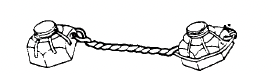
In a tapped hole the locking technique is normally on the fastener. One notable exception is the Spiralock7 tap shown in figure 1. The Spiralock thread form has a 30° wedge ramp at its root. Under clamp load the crests of the male threads are wedged tightly against the ramp. This makes lateral movement, which causes loosening under vibration, nearly impossible. Independent tests by some of the aerospace companies have indicated that this type of thread is satisfactory for moderate resistance to vibration. The bolt can have a standard thread, since the tapped hole does all the locking.
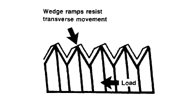
Figure 1.—Spiralock thread.
7 Distributed by Detroit Tap & Tool Company, Detroit, Michigan, through license from H.D. Holmes.
Locknuts
There are various types of locking elements, with the common principle being to bind (or wedge) the nut thread to the bolt threads. Some of the more common locknuts are covered here.
Split beam.—The split-beam locknut (fig. 2) has slots in the top, and the thread diameter is undersized in the slotted portion. The nut spins freely until the bolt threads get to the slotted area. The split “beam” segments are deflected outward by the bolt, and a friction load results from binding of the mating threads.
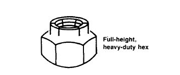
Figure 2.—Split-beam locknut.
Deformed thread.—The deformed-thread locknut (fig. 3) is a common locknut, particularly in the aerospace industry. Its advantages are as follows:
- The nut can be formed in one operation.
- The temperature range is limited only by the parent metal, its plating, or both.
- The nut can be reused approximately 10 times before it has to be discarded for loss of locking capability.
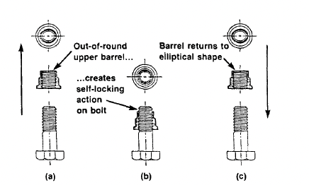
(a) Before assembly.
(b) Assembled.
(c) After withdrawal.
Figure 3.—Deformed-thread locknut.
Nylok pellet. —The Nylok8 pellet (of nylon) is usually installed in the nut threads as shown in figure 4. A pellet or patch projects from the threads. When mating threads engage, compression creates a counterforce that results in locking contact. The main drawback of this pellet is that its maximum operating temperature is approximately 250 °F. The nylon pellet will also be damaged quickly by reassembly.
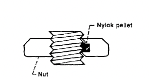
Figure 4.—Nylok pellet locknut.
8 Nylok Fastener Corporation, Rochester, Michigan.
Locking collar and seal. —A fiber or nylon washer is mounted in the top of the nut as shown in figure 5. The collar has an interference fit such that it binds on the bolt threads. It also provides some sealing action from gas and moisture leakage. Once again the limiting feature of this nut is the approximate 250 °F temperature limit of the locking collar. A cost-saving method sometimes used instead of a collar or nylon pellet is to bond a nylon patch on the threads of either the nut or the bolt to get some locking action. This method is also used on short thread lengths, where a drilled hole for a locking pellet could cause severe stress concentration.
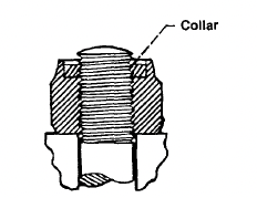
Figure 5.—Locking collar.
Castellated nut. —The castellated nut normally has six slots as shown in figure 6(a). The bolt has a single hole through its threaded end. The nut is torqued to its desired torque value. It is then rotated forward or backward (depending on the user’s preference) to the nearest slot that aligns with the drilled hole in the bolt. A cotter pin is then installed to lock the nut in place as shown in figure 6(b). This nut works extremely well for low-torque applications such as holding a wheel bearing in place.
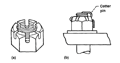
(a) Slots.
(b) Cotter pin locking.
Figure 6.—Castellated nut.
Jam nuts. —These nuts are normally “jammed” together as shown in figure 7, although the “experts” cannot agree on which nut should be on the bottom. However, this type of assembly is too unpredictable to be reliable. If the inner nut is torqued tighter than the outer nut, the inner nut will yield before the outer nut can pick up its full load. On the other hand, if the outer nut is tightened more than the inner nut, the inner nut unloads. Then the outer nut will yield before the inner nut can pick up its full load. It would be rare to get the correct amount of torque on each nut. A locknut is a much more practical choice than a regular nut and a jam nut. However, a jam nut can be used on a turnbuckle, where it does not carry any of the tension load.
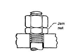
Figure 7.—Jam Nut.
Serrated-face nut (or bolthead). —The serrated face of this nut (shown in fig. 8) digs into the bearing surface during final tightening. This means that it cannot be used with a washer or on surfaces where scratches or corrosion could be a problem.
According to SPS Technologies, their serrated-face bolts (Durlock 180) require 110 percent of tightening torque to loosen them. Their tests on these bolts have shown them to have excellent vibration resistance.
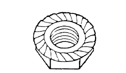
Figure 8.-Durlock nut.
Lockwiring. —Although lockwiring is a laborious method of preventing bolt or nut rotation, it is still used in critical applications, particularly in the aerospace field. The nuts usually have drilled corners, and the bolts either have throughholes in the head or drilled corners to thread the lockwire through. A typical bolthead lockwiring assembly is shown in figure 9(a), and a typical nut lockwiring assembly is shown in figure 9(b).
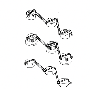
(a) Multiple fastener application (double-twist method, single hole)
Figure 9a.-Typical Bolthead Lockwiring.
(b) Castellated nuts on undrilled studs (double twist method)
Figure 9b.-Typical Nut Lockwiring
Direct interfering thread. —A direct interfering thread has an oversized root diameter that gives a slight interference fit between the mating threads. It is commonly used on threaded studs for semipermanent installations, rather than on bolts and nuts, since the interference fit does damage the threads.
Tapered thread. —The tapered thread is a variation of the direct interfering thread, but the difference is that the minor diameter is tapered to interfere on the last three or four threads of a nut or bolt as shown in figure 10.
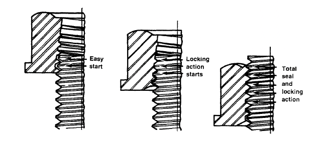
Figure 10.-Tapered Thread.
Nutplates. —A nutplate (fig. 11) is normally used as a blind nut. They can be fixed or floating. In addition, they can have most of the locking and sealing features of a regular nut. Nutplates are usually used on materials too thin to tap. They are used primarily by the aerospace companies, since their installation is expensive. At least three drilled holes and two rivets are required for each nutplate installation.
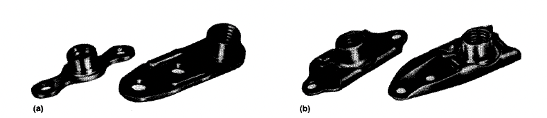
(a) Fixed. (b) Floating.
Figure 11.-Nutplate.
Locking Adhesives
Many manufacturers make locking adhesives (or epoxies) for locking threads. Most major manufacturers make several grades of locking adhesive, so that the frequency of disassembly can be matched to the locking capability of the adhesive. For example, Loctite 242 is for removable fasteners, and Loctite 2719 is for tamperproof fasteners. Other manufacturers such as Bostik, ND Industries, Nylock, 3M, and Permaloc make similar products.
Most of these adhesives work in one of two ways. They are either a single mixture that hardens when it becomes a thin layer in the absence of air or an epoxy in two layers that does not harden until it is mixed and compressed between the mating threads. Note that the two-layer adhesives are usually put on the fastener as a “ribbon” or ring by the manufacturer. These ribbons or rings do have some shelf life, as long as they are not inadvertently mixed or damaged.
These adhesives are usually effective as thread sealers as well. However, none of them will take high temperatures. The best adhesives will function at 450 °F; the worst ones will function at only 200 °F.
9 Loctite Corporation, Newington, Connecticut
Washers
Belleville Washers Belleville washers (fig. 12) are conical washers used more for maintaining a uniform tension load on a bolt than for locking. If they are not completely flattened out, they serve as a spring in the bolt joint. However, unless they have serrations on their surfaces, they have no significant locking capability. Of course, the serrations will damage the mating surfaces under them. These washers can be stacked in combinations as shown in figure 13 to either increase the total spring length (figs. 13(a) and (c)) or increase the spring constant (fig. 13(b)).
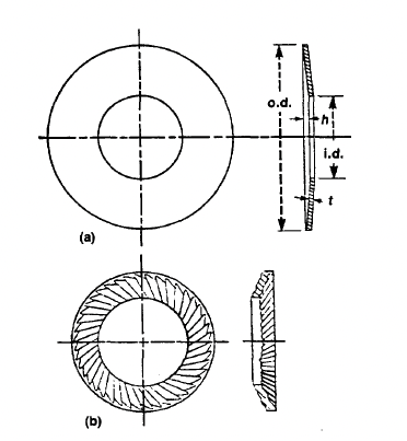
(a) Smooth. (b) Serrated.
Figure 12.-Types of Belleville Washers.
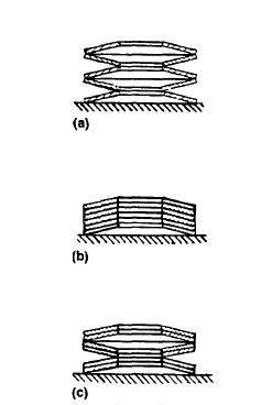
(a) In series.
(b) In parallel.
(c) In-parallel series
Figure 13.-Combinations of Belleville washers.
Lockwashers
Lockwashers The typical helical spring washer shown in figure 14 is made of slightly trapezoidal wire formed into a helix of one coil so that the free height is approximately twice the thickness of the washer cross section. They are usually made of hardened carbon steel, but they are also available in aluminum, silicon, bronze, phosphor-bronze, stainless steel, and K-Monel.
The lockwasher serves as a spring while the bolt is being tightened. However, the washer is normally flat by the time the bolt is fully torqued. At this time it is equivalent to a solid flat washer, and its locking ability is nonexistent. In summary, a lockwasher of this type is useless for locking.
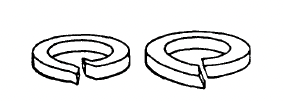
Figure 14.-Helical spring washers.
Tooth (or Star) Lockwashers
Tooth lockwashers (fig. 15) are used with screws and nuts for some spring action but mostly for locking action. The teeth are formed in a twisted configuration with sharp edges. One edge bites into the bolthead (or nut) while the other edge bites into the mating surface. Although this washer does provide some locking action, it damages the mating surfaces. These scratches can cause crack formation in highly stressed fasteners, in mating parts, or both, as well as increased corrosion susceptibility.
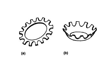
(a) Flat. (b) Countersunk.
Figure 15.-Tooth lockwashers.
Self-Aligning Washers
A self-aligning washer is used with a mating nut that has conical faces as shown in figure 16. Because there is both a weight penalty and a severe cost penalty for using this nut, it should be used only as a last resort. Maintaining parallel mating surfaces within acceptable limits (2° per SAE Handbook (ref. 4)) is normally the better alternative.
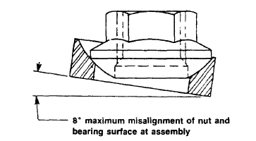
Figure 16.-Self-aligning nut.
Inserts
An insert is a special type of device that is threaded on its inside diameter and locked with threads or protrusions on its outside diameter in a drilled, molded, or tapped hole. It is used to provide a strong, wear-resistant tapped hole in a soft material such as plastic and nonferrous materials, as well as to repair stripped threads in a tapped hole.
The aerospace industry uses inserts in tapped holes in soft materials in order to utilize small high-strength fasteners to save weight. The bigger external thread of the insert (nominally 1/8 in. bigger in diameter than the internal thread) gives, for example, a 10-32 bolt in an equivalent 5/16-18 nut.
In general, there are two types of inserts: those that are threaded externally, and those that are locked by some method other than threads (knurls, serrations, grooves, or interference fit). Within the threaded inserts there are three types: the wire thread, the self-tapping, and the solid bushing.
Threaded Inserts
Wire thread.-The wire thread type of insert (Heli-coil10) is a precision coil of diamond-shaped CRES wire that forms both external and internal threads as shown in figure 17. The coil is made slightly oversize so that it will have an interference fit in the tapped hole. In addition, this insert is available with a deformed coil (fig. 18) for additional locking. The tang is broken off at the notch after installation.
The wire thread insert is the most popular type for repair of a tapped hole with stripped threads, since it requires the least amount of hole enlargement. However, the solid bushing insert is preferred if space permits.
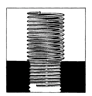
Figure 17.-Wire thread insert installation.
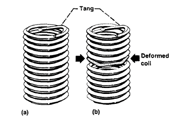
(a) Free running.
(b) Locking.
Figure 18.-Wire thread insert types.
10 Emhart Fastening Systems Group, Heli-Coil Division, Danbury, Connecticut.
Self-tapping.-Most of the self-tapping inserts are the solid bushing type made with a tapered external thread similar to a self-tapping screw (fig. 19). There are several different locking combinations, such as the Nylok plug (fig. 19(b)) or the thread-forming Speedsert11 deformed thread (fig. 20). An additional advantage of the thread-forming insert is that it generates no cutting chips, since it does not cut the threads. However, it can only be used in softer materials.
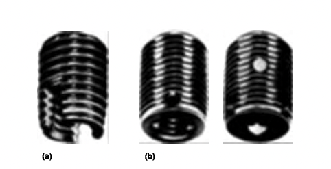
(a) Slotted
(b) Nylok
Figure 19.-Self-tapping inserts.
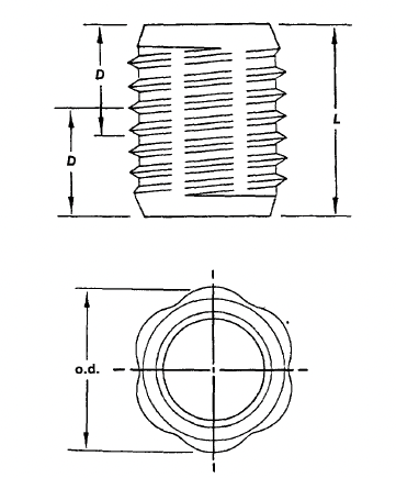
Figure 20.-Speedsert.
11 Rexnord Specialty Fasteners Division, Torrance, California
Solid bushing. -Solid bushing inserts have conventional threads both internally and externally. A popular type is the Keensert11 shown in figure 21. The locking keys are driven in after the insert is in place. Another manufacturer uses a two-prong ring for locking. These inserts are also available with distorted external thread or Nylok plugs for locking.
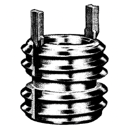
Figure 21.-Keensert.
Nonthreaded Inserts
Plastic expandable. -The most familiar of the nonthreaded inserts is the plastic expandable type shown in figure 22. This insert has barbs on the outside and longitudinal slits that allow it to expand outward as the threaded fastener is installed, pushing the barbs into the wall of the drilled hole. (See ref. 5.)
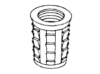
Figure 22.-Plastic expandable insert.
Molded in place. -This type of insert (fig. 23) is knurled or serrated to resist both pullout and rotation. It is commonly used with ceramics, rubber, and plastics, since it can develop higher resistance to both pullout and rotation in these materials than self-tapping or conventionally threaded inserts. (See ref. 5.)
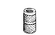
Figure 23.-Molded-in-place insert.
Ultrasonic. -Ultrasonic inserts (fig. 24) have grooves in various directions to give them locking strength. They are installed in a prepared hole by pushing them in while they are being ultrasonically vibrated. The ultrasonic vibration melts the wall of the hole locally so that the insert grooves are "welded" in place. Since the area melted is small, these inserts do not have the holding power of those that are molded in place. Ultrasonic inserts are limited to use in thermoplastics. (See ref. 5.)
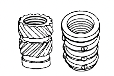
Figure 24.-Ultrasonic inserts.
Threads
Types of Threads
Since complete information on most threads can be found in the ANSI standards (ref. 6), the SAE Handbook (ref. 4), and the National Institute of Standards and Technology (formerly the National Bureau of Standards) Handbook H-28 (ref. 7) no thread standards will be included in this handbook. The goal here is to explain the common thread types, along with their advantages and disadvantages. The common thread types are unified national coarse (UNC), unified national fine (UNF), unified national extra fine (UNEF), UNJC, UNJF, UNR, UNK, and constant-pitch threads.
Unified national coarse. -UNC is the most commonly used thread on general-purpose fasteners. Coarse threads are deeper than fine threads and are easier to assemble without cross threading. The manufacturing tolerances can be larger than for finer threads, allowing for higher plating tolerances. UNC threads are normally easier to remove when corroded, owing to their sloppy fit. However, a UNC fastener can be procured with a class 3 (tighter) fit if needed (classes to be covered later).
Unified national fine. -UNF thread has a larger minor diameter than UNC thread, which gives UNF fasteners slightly higher load-carrying and better torque-locking capabilities than UNC fasteners of the same identical material and outside diameter. The fine threads have tighter manufacturing tolerances than UNC threads, and the smaller lead angle allows for finer tension adjustment. UNF threads are the most widely used threads in the aerospace industry.
Unified national extra fine. -UNEF is a still finer type of thread than UNF and is common to the aerospace field. This thread is particularly advantageous for tapped holes in hard materials and for thin threaded walls, as well as for tapped holes in thin materials.
UNJC and UNJF threads. -"J" threads are made in both external and internal forms. The external thread has a much larger root radius than the corresponding UNC, UNR, UNK, or UNF threads. This radius is mandatory and its inspection is required, whereas no root radius is required on uNc, UNF, or UNEF threads. Since the larger root radius increases the minor diameter, a UNJF or UNJC fastener has a larger net tensile area than a corresponding UNF or UNC fastener. This root radius also gives a smaller stress concentration factor in the threaded section. Therefore, high-strength (≥ 180 ksi) bolts usually have "J" threads.
UNR threads. -The UNR external thread is a rolled UN thread in all respects except that the root radius must be rounded. However, the root radius and the minor diameter are not checked or toleranced. There is no internal UNR thread.
UNK threads. -The UNK external threads are similar to UNR threads, except that the root radius and the minor diameter are toleranced and inspected. There is no internal UNK thread. According to a survey of manufacturers conducted by the Industrial Fasteners Institute, nearly all manufacturers of externally threaded fasteners make UNR rolled threads rather than plain UN. The only exception is for ground or cut threads.
Constant-pitch threads. -These threads offer a selection of pitches that can be matched with various diameters to fit a particular design. This is a common practice for bolts of 1-in. diameter and above, with the pitches of 8, 12, or 16 threads per inch being the most common.
A graphical and tabular explanation of UN, UNR, UNK, and UNJ threads is given on page M-6 of reference 8. A copy (fig. 25) is enclosed here for reference.
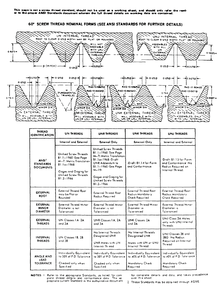
Figure 25.-Explanation of UN, UNR, UNK, and UNJ threads. (From ref. 8) Reprinted with permission of Industrial Fasteners Institute.
Classes of Threads
Thread classes are distinguished from each other by the amounts of tolerance and allowance. The designations run from IA to 3A and 1B to 3B for external and internal threads, respectively. A class 1 is a looser fitting, general-purpose thread; a class 3 is the closer-toleranced aerospace standard thread. (The individual tolerances and sizes for the various classes are given in the SAE Handbook (ref 4).)
Forming of Threads
Threads may be cut, hot rolled, or cold rolled. The most common manufacturing method is to cold form both the head and the threads for bolts up to 1 in. in diameter. For bolts above 1-in. diameter and high-strength smaller bolts, the heads are hot forged. The threads are still cold rolled until the bolt size prohibits the material displacement necessary to form the threads (up to a constant pitch of eight threads per inch). Threads are cut only at assembly with taps and dies or by lathe cutting.
Cold rolling has the additional advantage of increasing the strength of the bolt threads through the high compressive surface stresses, similar to the effects of shot peening. This process makes the threads more resistant to fatigue cracking.
Fatigue-Resistant Bolts
If a bolt is cycled in tension, it will normally break near the end of the threaded portion because this is the area of maximum stress concentration. In order to lessen the stress concentration factor, the bolt shank can be machined down to the root diameter of the threads. Then it will survive tensile cyclic loading much longer than a standard bolt with the shank diameter equal to the thread outside diameter.
Fatigue (Cyclic) Loading of Bolts
The bolted joint in figure 26 (from ref. 9) is preloaded with an initial load F;, which equals the clamping load Fe, before the external load F, is applied. The equation (from ref. 11) for this assembly is
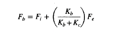
where Fb is the total bolt load. In this equation Kb is the spring constant of the bolt and Kc is the spring constant of the clamped faces. To see the effects of the relative spring constants, let R = KJ Kb. Then (from ref. 10)
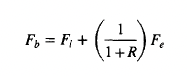
In a normal clamped joint Kc is much larger than Kb (R ""' 5.0 for steel bolt and flanges), so that the bolt load does not increase much as the initial external load F, is applied. (Note that the bolt load does not increase significantly until F, exceeds F;.)
In order to further clarify the effect of externally applied loads, a series of triangular diagrams (fig. 27, from ref. 11) can be used to illustrate loading conditions.
Triangle OAB is identical in all four diagrams. The slope of OA represents the bolt stiffness; the slope of AB represents the joint stiffness Goint is stiffer than bolt by ratio OC/CB.) In figure 27(a) the externally applied load F, (a) does not load the bolt to its yield point. In figure 27(b) the bolt is loaded by F, (b) to its yield point, with the corresponding decrease in clamping load to Fer• In figure 27(c) external load F,(c) has caused the bolt to take a permanent elongation such that the clamping force will be less than F; when F, (c) is removed. In figure 27(d) the joint has completely separated on its way to bolt failure.
Note that the flatter the slope of OA (or the larger the ratio OC/OB becomes), the smaller the effect F, has on bolt load. Therefore, using more smaller-diameter fasteners rather than a few large-diameter fasteners will give a more fatigue-resistant joint. Referring to figure 27(a), note that the cyclic (alternating) load is that portion above F;. This is the alternating load (stress) to be used on a stress-versus-load-cycles diagram of the bolt material to predict the fatigue life of the bolts. Note that an initial preload F; near the bolt yields minimizes cyclic loading.
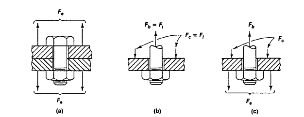
(a) Bolted flanges with external load.
(b) Free body with no external load.
(c) Freebody with external load.
Figure 26.-Fatigue loading of bolts.
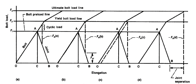
Figure 27.-Bolt external loading
Thermal Cyclic Loading of Bolts
If the bolt and joint are of different materials, an operating temperature higher or lower than the installation temperature can cause problems. Differential contraction can cause the joint to unload (or separate); differential expansion can cause overloading of the fasteners. In these cases it is common practice to use conical washers (see washer section of this manual) to give additional adjustments in fastener and joint loading.
Fastener Torque
Determining the proper torque for a fastener is the biggest problem in fastener installation. Some of the many variables causing problems are
- The coefficient of friction between mating threads
- The coefficient of friction between the bolthead (or nut) and its mating surface
- The effect of bolt coatings and lubricants on the friction coefficients
- The percentage of bolt tensile strength to be used for preload
- Once agreement is reached on item 4, how to accurately determine this value
- Relative spring rates of the structure and the bolts
- Interaction formulas to be used for combining simultaneous shear and tension loads on a bolt (Should friction loads due to bolt clamping action be included in the interaction calculations?)
- Whether "running torque" for a locking device should be added to the normal torque
TABLE IV.—COEFFICIENTS OF STATIC AND SLIDING FRICTION
[From ref. 12.]
|
|
|||||||||||||||||||||||||||||||||||||||||||||||||||||||||||||||||||||||||||||||||||||||||||||||||||||||||||||||||||||||||||||||||||||||||||||||||||||||||||||||||||||||||||||||||||||||||||||||||||||||||||||||||||||||||||||||||||||||||||||||||||||||||||||||||||||||||||||||||||||||||||||||||||||||||||||||||||||||||||||||||||||||||||||||||||||||
(1) Campbell, Trans. ASME, 1939; (2) Clarke, Lincoln, and Sterrett, Proc. API, 1935; (3) Beare and Bowden, Phil. Trans. Roy. Soc., 1935; (4) Dokos, Trans. ASME, 1946; (5) Boyd and Robertson, Trans. ASME, 1945; (6) Sachs, Z. Angew. Math. Mech., 1924; (7) Honda and Yamada, J. Inst. Metals, 1925; (8) Tomlinson, Phil. Mag., 1929; (9) Morin, Acad. Roy. des Sciences, 1838; (10) Claypoole, Trans. ASME, 1943; (11) Tabor, J. Applied Phys., 1945; (12) Eyssen, General Discussion on Lubrication, ASME, 1937; (13) Brazier and Holland-Bowyer, General Discussion on Lubrication, ASME, 1937; (14) Burwell, Jour. SAE, 1942; (15) Stanton, Friction; (16) Ernst and Merchant, Conference on Friction and Surface Finish, M.I.T., 1940; (17) Gongwer, Conference on Friction and Surface Finish, M.I.T., 1940; (18) Hardy and Bircumshaw, Proc. Roy. Soc., 1925; (19) Hardy and Hardy, Phil. Mag., 1919; (20) Bowden and Young, Proc. Roy. Soc., 1951; (21) Hardy and Doubleday, Proc. Roy. Soc., 1923; (22) Bowden and Tabor, The Friction and Lubrication of Solids; (23) Shooter, Research, 4, 1951.
(a) Oleic acid; (b) Atlantic spindle oil (light mineral); (c) castor oil; (d) lard oil; (e) Atlantic spindle oil plus 2 percent oleic acid; (f) medium mineral oil; (g) medium mineral oil plus 1/2 percent oleic acid; (h) stearic acid; (i) grease (zinc oxide base); (j) graphite; (k) turbine oil plus 1 percent graphite; (l) turbine oil plus 1 percent stearic acid; (m) turbine oil (medium mineral); (n) olive oil; (p) palmitic acid; (q) ricinoleic acid; (r) dry soap; (s) lard; (t) water; (u) rape oil; (v) 3-in-1 oil; (w) octyl alcohol; (x) triolein; (y) 1 percent lauric acid in paraffin oil.
Reprinted from Baumeister, et al. Mark's Standard Handbook for Mechanical Engineers, 8th ed., 1978, with permission of McGraw-Hill Book Co., Inc.
Development of Torque Tables
The coefficient of friction can vary from 0.04 to 1.10, depending on the materials and the lubricants being used between mating materials. (Table IV from ref. 12 gives a variety of friction coefficients.) Since calculated torque values are a function of the friction coefficients between mating threads and between the bolthead or nut and its mating surface, it is vitally important that the torque table values used are adjusted to reflect any differences in friction coefficients between those used to calculate the table and the user's values. Running torque should be included in the values listed in the tables because any torque puts shear load on the bolt. The torque values in table V have been calculated as noted in the footnotes, by using formulas from reference 13. (A similar table was published in Product Engineering by Arthur Korn around 1944.)
Higher torques (up to theoretical yield) are sometimes used for bolts that cannot be locked to resist vibration. The higher load will increase the vibration resistance of the bolt, but the bolt will yield and unload if its yield point is inadvertently exceeded. Since the exact yield torque cannot be determined without extensive instrumentation, it is not advisable to torque close to the bolt yield point.
Fastener proof load is sometimes listed in the literature. This value is usually 75 percent of theoretical yield, to prevent inadvertent yielding of the fastener through torque measurement inaccuracies.
Alternative Torque Formula
A popular formula for quick bolt torque calculations is T = KFd, where T denotes torque, F denotes axial load, d denotes bolt diameter, and K (torque coefficient) is a calculated value from the formula:
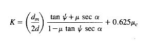
as given in reference 14 (p.378) where
dm thread mean diameter
ψ thread helix angle
μ friction coefficient between threads
α thread angle
μc friction coefficient between bolthead (or nut) and clamping surface
The commonly assumed value for K is 0.2, but this value should not be used blindly. Table VI gives some calculated values of K for various friction coefficients. A more realistic "typical" value for K would be 0.15 for steel on steel. Note that μ and μc are not necessarily equal, although equal values were used for the calculated values in table VI.
Torque-Measuring Methods
A number of torque-measuring methods exist, starting with the mechanic's "feel" and ending with installing strain gages on the bolt. The accuracy in determining the applied torque values is cost dependent. Tables VII and VIII are by two different "experts," and their numbers vary. However, they both show the same trends of cost versus torque accuracy.
Design Criteria
Finding Shear Loads on Fastener Group
When the load on a fastener group is eccentric, the first task is to find the centroid of the group. In many cases the pattern will be symmetrical, as shown in figure 28. The next step is to divide the load R by the number of fasteners n to get the direct shear load Pc (fig. 29(a)). Next, find Σr2n; for the group of fasteners, where rn is the radial distance of each fastener from the centroid of the group. Now calculate the moment about the centroid (M = Re from fig. 28). The contributing shear load for a particular fastener due to the moment can be found by the formula

where r is the distance (in inches) from the centroid to the fastener in question (usually the outermost one). Note that this is analogous to the torsion formula, ƒ = Tr/1, except that Pe is in pounds instead of stress. The two loads (Pc and Pe) can now be added vectorally as shown in figure 29(c) to get the resultant shear load P (in pounds) on each fastener. Note that the fastener areas are all the same here. If they are unequal, the areas must be weighted for determining the centroid of the pattern.
Further information on this subject may be found in references 16 and 17.
Finding Tension Loads on Fastener Group
This procedure is similar to the shear load determination, except that the centroid of the fastener group may not be the geometric centroid. This method is illustrated by the bolted bracket shown in figure 30.
The pattern of eight fasteners is symmetrical, so that the tension load per fastener from P1 will be P/8. The additional
TABLE V.-BOLT TORQUE TABLE VIL-INDUSTRIAL FASTENERS INSTITUTE'S TORQUE-MEASURING METHOD
[No lubrication on threads. Torque values are based on friction coefficients of0.12 between threads and 0.14 between nut and washer or head and washer, as manufactured (no special cleaning).] Size Root area, in.2 Torque range (class 8, 150 ksi, bolts•) 10-24 0.0145 23 to 34 in.-lb 10-32.0175 29 to 43 in.-lb ¼-20.0269 54 to 81 in.-lb ¼-4-28.0326 68 to 102 in.-lb 'l,o-18.0454 117 to 176 in.-lb 5l,o-24.0524 139 to 208 in.-lb 3/s-16.0678 205 to 308 in.-lb %-24.0809 230 to 345 in.-lb 7/16-14.0903 28 to 42 ft-lb 7/,o-20.1090 33 to 50 ft-lb ½-13.1257 42 to 64 ft-lb ½-20.1486 52 to 77 ft-lb 9/,o-12.1620 61 to 91 ft-lb 9/,o-18.1888 73 to 109 ft-lb 'l,-11.2018 84 to 126 ft-lb 'ls-18.2400 104 to 156 ft-lb ¾-10.3020 bJJ7 to 176 ft-lb ¾-16.3513 bJ39 to 208 ft-lb ?ls-9.4193 bJ84 to 276 ft-lb ?l,-14.4805 h213 to 320 ft-lb 1-8.5510 b276 to 414 ft-lb 1-14.6464 b323 to 485 ft-lb 1'/,-7.6931 b390 to 585 ft-lb 11/,-12.8118 b465 to 698 ft-lb 1¼-7.8898 h559 to 838 ft-lb 1 ¼-12 1.0238 b6S5 to 982 ft-lb aThe values given arc 50 and 75 percent of theoretical yield strength of a bolt material with a yield of 120 ksi. Corre-sponding values for materials with different yield strength:-. can be obtained by multiplymg these table values by the ratio of the respective material yield:-.trengths. bBolts of 0. 75-in. diameter and larger have reduced allow-ables (75 percent of normal strength) owing to inability to heat treat this large a cross section to an even hardne�s. Reprinted from Machine Design, Nov. 19. 1987. Copyright, 1987 by Penton Publishing, Inc.. Cleveland. OH.
TABLE Vl.-TORQUE COEFFICIENTS
[From ref. 8.] Preload measuring method Accuracy, percent Relative cost Feel (operator's judgment) ±35 Torque wrench ±25 1.5 Turn of the nut ±15 Load-indicating washers ±10 Fastener elongation ±3 to 5 Strain gages ±1 moment P2h will also produce a tensile load on some fasteners, but the problem is to determine the "neutral axis" line where the bracket will go from tension to compression. If the plate is thick enough to take the entire moment P2h in bending at the edge AB, that line could be used as the heeling point, or neutral axis. However, in this case, I have taken the conservative approach that the plate will not take the bending and will heel at the line CD. Now the Er� will only include bolts 3 to 8, and the rn's (in inches) will be measured from line CD. Bolts 7 and 8 will have the highest tensile loads (in pounds), which will be P =PT+ PM, where PT= P1!8 and An alternative way of stating this relationship is that the bolt load is proportional to its distance from the pivot axis and the moment reacted is proportional to the sum of the squares of the respective fastener distances from the pivot axis. At this point the applied total tensile load should be compared with the total tensile load due to fastener torque. The torque should be high enough to exceed the maximum applied tensile load in order to avoid joint loosening or leaking. If the bracket geometry is such that its bending capability cannot be readily determined, a finite element analysis of the bracket itself may be required. Combining Shear and Tensile Fastener Loads When a fastener is subjected to both tensile and shear loading simultaneously, the combined load must be compared with the total strength of the fastener, Load ratios and interaction curves are used to make this comparison. The load ratios are = - = - Rs(or R1) Allowable shear load Friction coefficient Torque coefficient, K Between threads, µ Between bolthead (or nut) and clamping surface, /le 0.05 0.05 0.074.10.10.133.15.15.189.20.20.250 Friction coefficient Torque coefficient, K Between threads, µ Between bolthead (or nut) and clamping surface, /le 0.05 0.05 0.074.10.10.133.15.15.189.20.20.250 Actual tensile load
- - Allowable tensile load
TABLE VIII.-MACHINE DESIGN'S TORQUE-MEASURING METHOD
[From ref. 15.]
- Typical tool accuracies Type of tool Element controlled Typical accuracy range, percent of full scale Slug wrench Turn I Flat Bar torque wrench Torque ±3 to 15 Turn 1/4 Flat Impact wrench Torque ±10 to 30 Turn ±101020° Hydraulic wrench Torque ±3 to ±10 Turn ±5 to 10° Gearhead air- Torque ±1010±20 powered wrench Turn ±5 to 10° Mechanical Torque::1:5 to 20 multiplier Turn ±2 to 10° Worm-gear torque Torque ±0.25 to 5 wrench Turn ± 1 to 5° Digital torque Torque ± 1/4 to 1 wrench Turn 1/4 Flat Ultrasonically Bolt elongation ±1 to 10 controlled wrench Hydraulic tensioner Initial bolt ±1 to 5 stretch Computer-controlled Simultaneous ±0.5 lo 2 tensioning torque and turn
- Control accuracies Element controlled Preload accuracy, percent To maximize accuracy Torque ±15 to ±30 Control bolt, nut, and washer hardness, dimensions, and finish. Have consistent lubricant conditions, quantities, applica-lion, and types. Use consistent snug torque. Control part geometry and finish. Use new sockets and fresh Iubes. Plot torque vs turn and compare to pre-viously derived set of curves. Control bolt hardness, finish, and geometry. Use "soft" bolts and tighten well past yield point. Use consistent snugging torque. Control bolt hardness and dimensons. Use bolts with flat, parallel ends. Leave transducer engaged during tightening operation. Mount transducer on bolt centerline. Turn ±15 to ±30 Torque and turn ±1010±25 Torque past yield ±3 to ±10 Bolt stretch ±1 to ±8 0 0 0 o-0---e• 0 0 0 0 0 0 0 o-0---e• 0 0 0 0 R
Figure 28.-Symmetrical load pattern.
The interaction curves of figure 31 are a series of curves with their corresponding empirical equations. The most conservative is R1 + R2 = 1 and the least conservative is Rf + R] = 1. This series of curves is from an old edition of MIL-HDBK-5. It has been replaced by a single formula, R'!; + R} = l, in the latest edition (ref. 18). However, it is better to use Rr + Rs = 1 if the design can be conservative with respect to weight and stress. Note that the interaction curves do not take into consideration the friction loads from the clamped surfaces in arriving at bolt shear loads. In some cases the friction load could reduce the bolt shear load substantially. n n R R ')(M= ')(M= + 1.0 R�+R�= / R�+R�=1-" / / / R)·5+R�=1_,, / / / R�+R�=1../ / / / / / / R1 +R�= 1.../ // / R + R = 1.../ 1 2 R�+R�= / R�+R�=1-" / / / R)·5+R�=1_,, / / / R�+R�=1../ / / / / / / R1 +R�= 1.../ // / R + R = 1.../ 1 2.8 "ct'.7 -2 6 (a) (b) Pc ' tt ' tt ct.5 0<= C C I-.3 .2.1 0.1.2.3.4.5.6.7.8.9 1.0
- R Shear, Rs (or R1)
Figure 29.-Combining of shear and moment loading. Figure 3!.-Interaction curves.
B D 0+ P2 0+ P, ©+ ®+ "-' 0+ 0+ ©+ 0+ A C r P, PM T P2 h tPr P, PM T P2 h tPr
Figure 30.-Bolted bracket.
The margin of safety 12 for a fastener from figure 31 is where N is the number (4, 6, 8, 10, 12) of the fastener. For example, the shank diameter of a no. 8 fastener is MS= ----1 Rs+ R!j. Diameter= 0.060 + 0.013(8) = 0.164 in. Fastener Groups in Bearing (Shear Loading) depending on which curve is used. However, note that Rs + R!j.< 1 is a requirement for a positive margin of safety. This formula also illustrates why high torque should not be applied to a bolt when the dominant load is shear. The margin of safety is calculated for both yield and ultimate material allowables, with the most critical value controlling the design. A material with a low yield will be critical for yield stress, and a material with a high yield will normally be critical for ultimate stress. Calculating Pullout Load for Threaded Hole In many cases a bolt of one material may be installed in a tapped hole in a different (and frequently lower strength) material. If the full strength of the bolt is required, the depth of the tapped hole must be determined for the weaker material by using the formula where P pullout load, lb dm mean diameter of threaded hole, in. (""' pitch diameter of threads) F, material ultimate or yield shear stress L length of thread engagement, in. The 1/3 factor is empirical. If the threads were perfectly mated, this factor would be ½, since the total cylindrical shell area of the hole would be split equally between the bolt threads and the tapped hole threads. The 1/3 is used to allow for mismatch between threads. Further information on required tapped hole lengths is given in reference 19. Calculating Shank Diameter for "Number" Fastener The shank diameter for a "number" fastener is calculated from Whenever possible, bolts in shear should have a higher shear strength than the bearing yield strength of the materials they go through. Since the bolts have some clearance and position tolerances in their respective holes, the sheet material must yield in bearing to allow the bolt pattern to load all of the bolts equally at a given location in the pattern. Note that the sloppier the hole locations, the more an individual bolt must carry before the load is distributed over the pattern. Bolts and rivets should not be used together to carry a load, since the rivets are usually installed with an interference fit. Thus, the rivets will carry all of the load until the sheet or the rivets yield enough for the bolts to pick up some load. This policy also applies to bolts and dowel pins (or roll pins) in a pattern, since these pins also have interference fits. Fastener Edge Distance and Spacing Common design practice is to use a nominal edge distance �f 2D from the fastener hole centerline, where D is the fastener diameter. The minimum edge distance should not be less than 1.5D. The nominal distance between fasteners is 4D, but the thickness of the materials being joined can be a significant factor. For thin materials, buckling between fasteners can be a problem. A wider spacing can be used on thicker sheets, as long as sealing of surfaces between fasteners is not a problem. Approximate Bearing and Shear Allowables In the absence of specific shear and bearing allowables for materials, the following approximations may be used: Alloy and carbon steels: Fsu = 0.6 F,u Stainless steels: Fsu = 0.55 F1u where Fsu is ultimate shear stress and F1u is ultimate tensile stress. Since bearing stress allowables are empirical to begin with, the bearing allowable for any given metallic alloy may be approximated as follows: Diameter= 0.060 + 0.013 N 12Margin of safety is defined as Allowable load (Stress)
- 1 Actual load (Stress) X Safety factor where Fbu is ultimate bearing stress, Fby is yield bearing stress, and Fry is tensile yield stress. Proper Fastener Geometry Most military standard (Ms) and national aerospace standard (NAS) fasteners have coded callouts that tell the diameter, grip length, drilling of the head or shank, and the material (where the fastener is available in more than one material). Rather than listing a group of definitions, it is easier to use the NAS 1003 to NAS 1020 (fig. 32) as an example to point out the following:
- The last two digits give the fastener diameter in sixteenths of an inch.
- The first dash number is the grip length in sixteenths of an inch.
- The letters given with the dash number indicate the head and/or shank drilling. In addition, an identifying letter or dash number is added to indicate the fastener material. However, this systematic practice is not rigidly followed in all MS and NAS fastener standards. Shear Heads and Nuts In the aerospace industry the general ground rule is to design such that fasteners are primarily in shear rather than tension. As a result, many boltheads and nuts are made about one-half as thick as normal to save weight. These bolts and nuts are referred to as shear bolts and shear nuts, and care must be used in never specifying them for tension applications. The torque table values must also be reduced to one-half for these bolts and nuts. Use of Proper Grip Length Standard design practice is to choose a grip length such that the threads are never in bearing (shear). Where an exact grip length is not available, the thickness of the washers used under the nut or bolthead can be varied enough to allow proper grip. Bolthead and Screwhead Styles Although the difference between bolts and screws is not clearly defined by industry, at least the head styles are fairly well defined. The only discrepancy found in figure 33 is that the plain head, with a square shoulder, is more commonly called a carriage bolthead. The angle of countersunk heads (flat) can vary from 60° to 120°, but the common values are 82 ° and 100°. Counterfeit Fasteners In the past two years a great deal of concern and publicity about counterfeit fasteners has surfaced. The counterfeit case with the most documentation is the deliberate marking of grade 8.2 boron bolts as grade 8 bolts. Grade 8.2 bolts are a low-carbon (0.22 percent C) boron alloy steel that can be heat treated to the same room-temperature hardness as grade 8 medium-carbon (0.37 per-cent C) steel. However, the room- and elevated-temperature strengths of the grade 8.2 bolts drop drastically if they are exposed to temperatures above 500 °F. Grade 8 bolts can be used to 800 °F with little loss of room-temperature strength. Other fasteners marked as MS and NAS but not up to the respective MS or NAS specification have shown up; however, documentation is not readily available. Since these fasteners are imported and have no manufacturer's identification mark on them, it is not possible to trace them back to the guilty manufacturer. U.S. Customs inspections have not been effective in intercepting counterfeit fasteners. Another problem with fasteners has been the substitution of zinc coating for cadmium coating. If a dye is used with the zinc, the only way to detect the difference in coatings is by chemical testing. Federal legislation to establish control of fastener materials from the material producer to the consumer is being formulated. Bolthead Identification Identifying an existing non-Ms, non-NAS, or non-Air Force-Navy bolt is usually a problem. Each manufacturer seems to have a different system. Frank Akstens of Fastener Technology International magazine (ref. 20) has compiled a good listing of several hundred "common" bolts. His entire compilation is enclosed as appendix A of this report. An international guide to bolt manufacturer's identification symbols has also been published by Fastener Technology International magazine. Fastener Strength Allowable strengths for many types of fasteners are given in MIL-HDBK-5 (ref. 18). Ultimate shear and tensile strengths of various threaded fasteners are given in appendix B of this report. NATIONAL AEROSPACE STANDARD Al:11105PACI: IN0USTltlE5 ASSOCIATION 01 AMERICA INC_ t7Z� CE SALCS STRCCT " W WASHINGTON C C 20036 IDENTIFY PER LENGTH,.015,- NASJ347 TY1'E II GRIP, l<>M • J, MOM,).01� H DIA C GRIP (a)TT.020,.005 C/2 •.010 (;) R DETAIL A POINT TO SE FL AT ANO CHAMFERED. LENGTH OF POINT TO FIRST COMPLETE THREAD - U MAX Oi.AMFER 15° TO CRILL K WHEN SPECIFIED. H OPTIONAL BREAK SHARP EDGES © IASIC TMIUD • I C D H(o) • M(b) R CRADJ T X,- z Nl'IIIIU. MAX MIN MIN """ •.OJO • 010 ltAX MR; PART UNJF-lA DIA.:,.01, llf DIA DIA Di. RII '-' (d) {d) '"
- 000 -.ooo NASIOOl 1900-12.1195,,. !67.125 4l m.l66 046.070.020 010 4SI 05 oo, 0040.0040 NA.!1004 ll00-21 I 2495 439.4)0.U6,, m 112.046 076.020 010.5.W.o,,.006.0045.00]0 2470 I NASIOOJ lllS-24 3120.501.-t9l.lBI _,.., l59 070.O7c,.020 010.632 o, I 008 004' 00}0 ·'°''.,.. ·" I I.nu _,,. I NA.11006.)150-24.l?lO.219 ·" lll OB.070 106 -OH Oil 661 I"' I 009 10060 002' NA.$1007 •lH-20 070.... 679 250.19....484.070 l(l•.OB l 015,., 1 011 f 010 I0060.DOB.oo I.4995 "' _.,.., I NA.Sll'lll.J000-20 4970 1,1 lll '10 609 I 0,0 106 1.010.OlV I 08 i Oll i,0060 0020 I I NASI009.J6l5- II I.5615 _.,,I.165 lll 1.01 m.6Sb I 070 1'1 I 0:15 I 020 I 9•• I o• 0060 0020.!i.51.5 I l I °" NA.$1010 6250-11.,210.9)9 9ll)U 1109 191 7)4 o,o 141.040 i025 p_042 I o, 01' 0060 0020.u,o NASIOl2.7500-16.7"190 1.064 I I 053 406 l ll 1.02).17' o,o i 141 04'.030 1.IM.IP lou 0090 0020 NASIOl,1 17'0-lol.11•0 L2Sl 1.n,.469,.... 1.210... 141 050.0).5 1.3'6 II 020.0090.0020 '"'°.1710 010 1 JrrriA.S101• l.0000-12....., I I...... 1.427 !}I 109' o,oI 1'1 060.04l 1.411 ll 0:2 00,0 0020 © �)d)IV M.,,(Y".996().... I.."' I i NASIDII 1.IB0-12 1.1240 1.627 I 61'.n, Ill! U851.1111 010, \41I070 I) Oll I.OO'>fl 0020 1.1200 °"I'-'" I I NA.51020 1.1500-12 1.2490 1.801.,. 2.10 1.712 1.)15 070 141 01' 060 1146 l} Oll 0120 0020 1 2,so'-'"
- �JIY © NASIOIM.IJ.IACTTVEFOltDESKiNAFTUJVl.'r'l,191'9 LIST OF CURRElliT SHFFTS I so. I Rr I CUSTODIAN NATIONAL AEROSPACE STANDARDS COMMITTEE PROCUREMENT 5PECIFICATlO"' NONI: BOLT - MACHINE HEXAGON HEAD, NON MAGNETIC, & HEAT RESISTANT STANDARD PART NAS 1003 THRL' 1020 SHEET l OF 3 IDENTIFY PER LENGTH,.015,- NASJ347 TY1'E II GRIP, l<>M • J, MOM,).01� H DIA C GRIP (a)TT.020,.005 C/2 •.010 (;) R DETAIL A POINT TO SE FL AT ANO CHAMFERED. LENGTH OF POINT TO FIRST COMPLETE THREAD - U MAX Oi.AMFER 15° TO CRILL K WHEN SPECIFIED. H OPTIONAL BREAK SHARP EDGES © IASIC TMIUD • I C D H(o) • M(b) R CRADJ T X,- z Nl'IIIIU. MAX MIN MIN """ •.OJO • 010 ltAX MR; PART UNJF-lA DIA.:,.01, llf DIA DIA Di. RII '-' (d) {d) '"
- 000 -.ooo NASIOOl 1900-12.1195,,. !67.125 4l m.l66 046.070.020 010 4SI 05 oo, 0040.0040 NA.!1004 ll00-21 I 2495 439.4)0.U6,, m 112.046 076.020 010.5.W.o,,.006.0045.00]0 2470 I NASIOOJ lllS-24 3120.501.-t9l.lBI _,.., l59 070.O7c,.020 010.632 o, I 008 004' 00}0 ·'°''.,.. ·" I I.nu _,,. I NA.11006.)150-24.l?lO.219 ·" lll OB.070 106 -OH Oil 661 I"' I 009 10060 002' NA.$1007 •lH-20 070.... 679 250.19....484.070 l(l•.OB l 015,., 1 011 f 010 I0060.DOB.oo I.4995 "' _.,.., I NA.Sll'lll.J000-20 4970 1,1 lll '10 609 I 0,0 106 1.010.OlV I 08 i Oll i,0060 0020 I I NASI009.J6l5- II I.5615 _.,,I.165 lll 1.01 m.6Sb I 070 1'1 I 0:15 I 020 I 9•• I o• 0060 0020.!i.51.5 I l I °" NA.$1010 6250-11.,210.9)9 9ll)U 1109 191 7)4 o,o 141.040 i025 p_042 I o, 01' 0060 0020.u,o NASIOl2.7500-16.7"190 1.064 I I 053 406 l ll 1.02).17' o,o i 141 04'.030 1.IM.IP lou 0090 0020 NASIOl,1 17'0-lol.11•0 L2Sl 1.n,.469,.... 1.210... 141 050.0).5 1.3'6 II 020.0090.0020 '"'°.1710 010 1 JrrriA.S101• l.0000-12....., I I...... 1.427 !}I 109' o,oI 1'1 060.04l 1.411 ll 0:2 00,0 0020 © �)d)IV M.,,(Y".996().... I.."' I i NASIDII 1.IB0-12 1.1240 1.627 I 61'.n, Ill! U851.1111 010, \41I070 I) Oll I.OO'>fl 0020 1.1200 °"I'-'" I I NA.51020 1.1500-12 1.2490 1.801.,. 2.10 1.712 1.)15 070 141 01' 060 1146 l} Oll 0120 0020 1 2,so'-'"
- �JIY © NASIOIM.IJ.IACTTVEFOltDESKiNAFTUJVl.'r'l,191'9 LIST OF CURRElliT SHFFTS I so. I Rr I CUSTODIAN NATIONAL AEROSPACE STANDARDS COMMITTEE PROCUREMENT 5PECIFICATlO"' NONI: BOLT - MACHINE HEXAGON HEAD, NON MAGNETIC, & HEAT RESISTANT STANDARD PART NAS 1003 THRL' 1020 SHEET l OF 3 .:: e ,r. "' z �.>.. ct Pubt•lhei Ind Chttrllbut9d b-.i...... Qf'liM $11.....dlA, IIOC'illlOn Inc -111...,AD•.C..N•OU A..-olPKI lnc:lultnft Auoc.1at1on ol Amenca. Inc. 1979 C. < < a..J < I? <
Figure 32.-National aerospace standard for proper fastener geometry.
NATIONAL AEROSPACE ST.�J�D.t..RD AEROSPACE INOU�T�l�S ASSOCIA,ION OF AW.�r,1;;,, rr-:: CODE BASIC PART NU'.'-f!l[:R DESIG!\ATES.. o�m-1;.;, DlMiaETEk. DASH:.;UA:J!E!l DESIGNt.1"ES GRIP AND !.f.1•:G1 P. (S!:l:: SP.ET J,..um "A" T'J DASH NiJMDER FOP. UNDR]i..;.ED;'!')'�-ADD "H'' TO DASH NUMllER "'OR DRILLED �£p_i) -::>N' 'I. 1\0 CODE LEITER DESIGNATES DRILLED SHANK Ci-ILY. EXAMPLE NAS!OOJ-8. 1900 DlA.',!ETE!! BOLT..500 G!W', DRILLED SHANK ONLY. K.\S1003 -8A.l 900 fltAMETER &0!.T.. 508 CR!?, UNDklLLED. Nt,,Sl0l'3-8H.190" l)IAMETi:I< bOLT.. SOt! GRll', DRILLED HEAD ONL '. MATERlAL CRES, A-286 SPEC AMS5735 OR AMSSn:.n:.()i_w/.,/Q'/,AJt\J2'/�;£y.(y.hcEPT ULTIMATE0 TENSILE STRFNGTll 140,000 rs!),,tN!Mt:M AT ROO'd TEMPERATURE, FABRICATED TO AMS7�78. flN!SH· CLEAN AND PASS!VATE !N ACCORDANC!' 'dTH_/4i,';/5<fp£/ QC)-P-.1S (i"; '--' REFERENCE LJ!MU/�IOSS ARE FOR DESIG', ruRPOSES ()NL y At-:D NOT AN INSP!,CTION REQl.i:RE!,![',T, 2. MAGNETIC PERMEAUILITY SHALL BE USS Tl:AN 2.0 I AIR • l.il, FOR A FIELD STRENGTH H: 200 OERSTEDS (MAGNETIC PERMEABILITY INulCATOr,,;-,,:,ii�-!-! 7�14 OR EQUIV,;L[ i'IT l.1 ROLTS SHALL Bf I REE f!>.O�, llCl<RS A,,D '.it.''.'l:RS. 4. THF�E P.OLTS ARE lts:TH,':)!:f1 •'OF- 1:,;-:,-.-, ',;>t �- ',Tt:RLS IJP TO I 2(•j F. w 5. GRIP:.F:"JGT H [1{0�1 >j(>t.R �lliE Cf- f-j[hL ro E:'-',.' or f Ult CYLINDRICAL f>OR·:10:--. or: SHANK. G G,cl I. "H" UIA.'IAXIMt=M NU: TO [XC[G: "'il"': •1.1::H,!Li! 01.:,;.1101' OF HEAD NO", LESS THAN "H". rd: 8. CONCF:-ITRICITY· "i-i"" A:--:::, "A" UIAh'.�.E'.' ·,-.-,,,l'.�: '";:" V ALlJES TlR "A" AND THREAD PITCH DIAMETER 11.1 nm:"") •• VALUES TIF:. i<I 9. SHANK STRAIGHTNESS. WITHJ"s "Z" '.-L,',-.� "'."if-. l'cl(,sc;: OF L'�!\GTH IgI JO. BEARING SURFACE SQUARENESS: Y.'(11Jfr,;.V'_, TIR WITH SHAAK. Ii. DIML''SIONS 11' INUJLS. JOLZ.RA�([S �-t'L!.SSOTi-lTH1�·:sr J?rr::-,· ·, A'\°l�Lt S:(c 0, .w.. < .J , ' II: NAS 1003 THRU 1020 l� �··--· SHEET 2 I Nlit1or,al Sl.and.,d, Auoc.. �ro,n Inc,1.21 Au¢y A.,. Wht11nvton O C 20014
Figure 32.-Continued.
0, A.,..o..-. h'lduwtr.-..A.aaccleUOfl of Al'ft9"1C.I. tnc NATIONAL AEROSPACE STANDARD AEROSPACE INOUSTRIES ASSOCIATION Of' AMERICA. INC.. 172� OE SALES STREET N W W•SHl,..GTO". 0 C 200�6 . 712 ."." . rot).870.96? l.072 l.16� �.\li. ��L�l 1 l.75< '.c... I.�'Jl.a, 1.0·�::, l.,c. l,?1.0 l.< 1,cL'- 1 Q. ?,Ql4.Ql'.�, 1.·=, l.l<n l.292 L•'o l.606 l. l l:,,.;co 2.0"': ·' l l.O'-" l. l.100 l.1'2 l.194 l.161 l.24'> l.'•2 j.1.47 l.'>42 1.h�C LH'-" 1.Q8"1 2.1<J\ 2.'46 l.22, 1.,u l.•04 l. m l.oOl. 1:1•1 1:-<ll" 2.041 2.220 2.,nP- 10 2 l.l b l.lt:>9 l.257 l.2tlb l. 70 l.W> l. '2 l. '.67 1.81• 1:qtl1 2.l.C'<, 2.2f• 2.•71 f-���;:-+-'-:m:+-l'°l:.,:!m�-+-,��:;��•:r.2+...;t;-:�;i2.,,�J-+-ii.�:.:S#'l��2i-'-:�□�<+.:.��:'�.��04"_!.i.:!:O��-���:::;,,,�o'--+-'ti-:0:!1;.!C-!-t-'�§-'::.Sl�n,;+��§-':����Cl+�;:..�::-�,l;��;,.:.:-:?•,::'�r,: 13 12 1,, 1. 'l' J..44� l.47t; 1. 87 l..,.. l. 7�0 l. lio,4 2.001 2.l� 2.2Q� 2.1&70 2 _t:,c;8 1 °" °" j', •. n, l.iolQ l."' l.S70 l.6ol 1.1r1;. MO 1.�, •·'"' 2.12� 2.2,c;i; 2.•1° 2. 2.7oi. 16 1.000 1.1ot1 1."',lc 1.012 L""' 1.,4• 1. >42 l."4' 2.oi.2 2.1Aa 2.'"-" 2.•A1 2. •• 2.�--, jT l.Of>2 l.s• 1."-"" l.h°'-' l-12� 1.11<17 l. 2JY1C 2,lnl. 2.2<). 2.•!A 2,cJ., 2.020 2."°" l� l.12S l.'-' 1.669 l.«7 l.7tlb 1.870 l.'lt7 2.072 2.167 2.'14 2,481 2.606 2.,P, 2.01: 19 l.ltlll 1.~ 1.112 1.5:': l.BSl 1.cr 2.0o 2.115 2.2,c 2:17, 2.,1.1. 2.�c 2. 0·-,.o,.. 20 l.2�0 1.1 l 1.79• l.882 l.911 1.00< 2.C>C 2.1cr 2.292 2.41C 2.606 2.7'1 2.c,oP ncr I 21 1.112 1.,01 1. ""K l.94J.1 l.Q'"l 2.oc,,; c'.l 2.2.c.c 2.1.cJ.. 2.c.c:.. 2.-'-""-M. 2.'?a, 2,070 �.1i:;P: 1 22;.17, l.MS,, l.' 10 2.007 2.016 2.120 2.21 2.l22 2.•l.7 2.'--'" 2.7ll 2.i's,; •.0'- l,22l 2 l.•u I l.91', l.<1112 2.070 2.101 2.16-• 2.2f\ 2.lFS 2.4&o 2.62" 2.7Cl. 2.Cls 1.00,, <.20. 2 11. OC 1.�l 2.'ll...1.1. 2.1'.l.2 2.lol. 2.21ic; 2.i42 2.41."" 2,c,i..2 2.6 •...c. 2.ec.:5 2:a:r1 �..!.1;,tl l. rY;?,p;c; 2-✓.? 2.1:2'(, 2,1. 2,L·,· I 2.C.'l·);;J.-;.c. 2,.,.<0 2,f'">·;,Ql..it �.i�.:- I <.,ii•.:::
- ·u,Q 2.21.l 2.2'� 2,H'U :?,it. ·1 2.4::.ic, I :',C..0'2 2.61 2,7Q? 2,cno 1.,106 "',21.2 1,Lr--J;.
- .721 l 1.,,� 2.�1 2.1.1e 2."J?G 2. C"•l �.otH 1 2.ibC 2. ... 2....0.;,l.2"! 1..204 1,... 1:... �-c; • 12:;1,1• � 2.1"1';> 1 2. '11'11 �.7ka; ?,=>-.. 2. 7 1.,0i.? �:1�:::,.,.. i;.. �Ji]-:, 1..�c:.� 1 2 1 2 1--fi!---+:�a-':��,-!�7',,;:'C•+-'�s':''r1:·-i: +-l�;-':�1ci,r-'-;-;-!':-'aoo:=:7a--H;:-':�o�:�,giH-�,.:.�':,120:;:;-+1�'"":2°":�,-;-+--''-'-'"',22.;wr-",''"':f"'�"'��-l.:'"'�::.;·..,:w.-l.�":�"",'';��----'"--:e..:.r.',."".�----:"":"'f°',-=-;....i..,..:i":"�;z;°"2=-:...... 2.500 2.Q l:i..044,.112 1.16; 1..21..<::;.;42 1,4!.- I �.�'-2.,,:,F,..:; -◄.:''..:..; - •.::i81 T L..1c.E, 1..•i.c 1.1.r, 3.16<; 1.2C."' 1..2'bt:!;..·nr, -...W:"' -.",72 l l.,M7,81&. I 1.,Qr..,. "-!Ck. l...2t1-:: L,li.".'i
- 4 2. "'>I.J "° -.2 1 1,2q-" l..l,!::l,2 �.41,Lt..C.", �.�C/2 1.c::r 1 7.792.,q1.c l 1..10c 1.,21,1 l..4(•:- 1 l..,c,.' I:i.1.1.19 -L�07 1..-..-:i.�.u2'·�} 1.-1- -=.�C 1..Ql..,.,.,06'- 4,2 l: T;, v.... C:-n....72: t 4b '.ooc 0 1.12 .<U. 1.612,.F,E-,.71.5 1.S..2 >.Ql.7 T I..Ol.2 •. i"E:l •• -' 4, di •�<t "·""" I,Mc; -:i.,7c:,-, -.:&9,R7C l.,�.,. l...m? I;.. 1�.., "•' �-.i.:: l 1.. """- 1,.,7"5'; r.;o-t·,:.7Q;,. '.. �-- 1.Ql'l: !. �: I.. •c-, I;.. '.Jo-::,.4-a L;:.. I...;• -.,.Y"I,.. c..,:-i� i..ocn 4.c;5 r i..1u 4.211 i..�22 L..1.1: 4.. 1...- 1 '-· u--.,;,o;-:: "'.22: 1 0,.150 <:,q��,044... lot 4.l�Q 4.V,/, • 4.414 i..11.2 i...1c1... 2-.'-; i.. l.42 i.,l.,.i.."7 ! i..,c;42 '°· IQ 4;;.. 4. 8! �.1c.c: <i.-...o 1 4.257 •.2F.F. T 4.170 • I..r..,, 4.<72 L..�7 4. l• c.O: l <.l"' •.275, s.• ·: 7 at, 4.00C 4,125 4.612 I 4.M1 4.74"-, 4.E..L.�. q4- (..Qli2 C..lR(;.c.-� '-.�Fl c;·""'"'t 4.7'">7 { �.7.'1n 1....Q,-,O T-4,-Qh., 1 '1-.072,16-:' c: 1i...c;.�::.. c: � c:,71;--: 74... 2 '1.00" C,,Q";\E! 'i.120 l <..2!.- I 22.L.:...:.n2 s.101 S.24" s.,1.2., 1.si.2 s. Il:=: l c:-. � f-.c-:-1. 70 5.2 l 7� I�.,-,, 5,,,,; co 5.000 5.i.81 s.� 5.419 5.,- ',.u,., S.507 5.62 t:;.161 i:;-.,.._ c.�::r.2 <.s I s.,<;:,c <.7!7 I. 122 5.00 5.71,5 5.81-2: 5..,.1 .·r'-T.::' <.91� 6./\l.:> c;, ·c,,.l� 6,..,_.2 l o.18Q.; o 6,2 l 6,L1.rv o. 6.<1' ·o:. 1 o:058 C,c:a.,;: 6.72: ,.,. 5. ·�
- ' l ·""y .D..1 2 .,o .oru ·""' .11, .2:l ,l,.2 ' 7.w ,.� I 7.2.2,,: z Vi > "II': llo\SH !IO. INDIC:AUS GRIP l.EIIGTH IN.O6"S INCREME!'.TS INTERMEDIATE OR LONGER LENGTHS HAY BE ORDERED BY USE OF PROPER DASH MO. Pubhlhed •nd dtitrib..,Hd by Natior-,•I StandatO\ Auoci•tion Inc "827 RUllbY A,.. w_,.,,..on. O C 2001'
Figure 32.-Concluded.
NAS 1003 THRU 1020 Ae,oJp,ace lndust,un Auoc1a11on of Ameru:.1 Inc 1979 All,iqhu rne,wed ' lol � < .J < > E L L < ■ ■ -Oval -Fillister Washer Hex ........... - •■• T........... - •■• T
- -
-
undercut, trim, and undercut, trim, and Pan Binding Truss Plain Hex washer 100° heads. (carriage)
Figure 33.-Bolthead and screwhead styles.
and Lockbolts
Rivets and Lockbolts
Rivets
Rivets are relatively low-cost, permanently installed fasteners that are lighter weight than bolts. As a result, they are the most widely used fasteners in the aircraft manufacturing industry. They are faster to install than bolts and nuts, since they adapt well to automatic, high-speed installation tools. However, rivets should not be used in thick materials or in tensile applications, as their tensile strengths are quite low relative to their shear strengths. The longer the total grip length (the total thickness of sheets being joined), the more difficult it becomes to lock the rivet. Riveted joints are neither airtight nor watertight unless special seals or coatings are used. Since rivets are permanently installed, they have to be removed by drilling them out, a laborious task. General Rivet Types The general types of rivets are solid, blind, tubular, and metal piercing (including split rivets). From a structural design aspect the most important rivets are the solid and blind rivets. Solid rivets.-Most solid rivets are made of aluminum so that the shop head can be cold formed by bucking it with a pneumatic hammer. Thus, solid rivets must have cold-forming capability without cracking. A representative listing of solid rivets is given in table IX (ref. 21). Some other solid rivet materials are brass, SAE 1006 to SAE 1035, 1108 and I 109 steels, A286 stainless steel, and titanium. Note that the rivets in table IX are covered by military standard specifications, which are readily available. Although most of the solid rivets listed in table IX have universal heads, there are other common head types, as shown in figure 34. However, because the "experts" do not necessarily agree on the names, other names have been added to the figure. Note also that the countersunk head angle can vary from 60° to 120° although 82° and 100° are the common angles.
TABLE IX.-ALUMINUM AND OTHER RIVET MATERIALS
[From ref. 21.]
Material
Rivet designation Rivet heads available Applications 2117-T4 AD Universal (MS20470) 100° Flush (MS20426) General use for most applications 2024-T4 DD Universal (MS20470) 100° Flush (MS20426) Use only as an alternative to 7050-T73 where higher strength is required I 100 A Universal (MS20470) 100° Flush (MS20426) Nonstructural 5056-H32 B Universal (MS20470) 100° Flush (MS20426) Joints containing magnesium Mone! (annealed) M Universal (MS20615) 100° Flush (MS20427) Joining stainless steels, titanium, and Inconel Copper (annealed) 100° Flush (MS20427) Nonstructural 7050-T73 E Universal (MS20470) 100° Flush (MS20426) Use only where higher strength is required The sharp edge of the countersunk head is also removed in some cases, as in the Briles 13 BRFZ "fast" rivet (fig. 35), to increase the shear and fatigue strength while still maintaining a flush fit. Blind rivets.-Blind rivets get their name from the fact that they can be completely installed from one side. They have the following significant advantages over solid rivets:
- Only one operator is required for installation.
- The installation tool is portable (comparable to an electric drill in size). 13Briles Rivet Corporation, Oceanside, California. Button Truss (brazier) Flat Countersunk (flush) Pan (universal) u u Shear-bearing area Shear-bearing area
- They can be used where only one side of the workpiece is accessible.
- A given-length rivet can be used for a range of material thicknesses.
- Installation time is faster than with solid rivets.
- Clamping force is more uniform than with solid rivets.
- Less training is required for the operator. Blind rivets are classified according to the methods used to install them:
- Pull mandrel
- Threaded stem
- Drive pin Specific types (brands) of blind rivets are covered in subsequent sections of this manual. Pull-mandrel rivets: This rivet is installed with a tool that applies force to the rivet head while pulling a prenotched serrated mandrel through to expand the far side of the tubular rivet. When the proper load is reached, the mandrel breaks at the notch. A generic pull-mandrel rivet is shown in figure 36. Threaded-stem rivets: The threaded-stem rivet (fig. 37(a)) has a threaded internal mandrel (stem) with the external portion machined flat on two sides for the tool to grip and rotate. The head is normally hexagonal to prevent rotation of the tubular body while the mandrel in being torqued and broken off. Drive-pin rivets: This rivet has a drive pin that spreads the far side of the rivet to form a head, as shown in figure 38. Although drive-pin rivets can be installed quickly, they are Rivet inserted Start setting
Figure 36.-Pull-mandrel rivet. (From ref. 5.)
usually not used in aerospace applications. They are used primarily for commercial sheet metal applications. Tubular rivets.-Tubular rivets are partially hollow and come in a variety of configurations. The generic form has a manufactured head on one side and a hollow end that sticks through the pieces being joined. The hollow end is cold formed to a field head. Since extensive cold forming is required on these rivets, they must be extremely ductile and are consequently made of low-strength materials. They are normally used for commercial applications rather than in the aerospace industry. Some specific types of tubular rivets are
- Compression
- Semitubular
- Full tubular Inserted Installed (b) Inserted ,r- Hexagonal head°'- Installed
Figure 38.-Drive-pin rivet. (From ref. 5.)
One-piece body. (From ref. 5.)
- Two-piece body. (From ref. 22.) Figure 37.-Threaded-stem rivets.
Figure 39.-Compression tubular rivet. (From ref. 5.)
Compression tubular rivets: A compression tubular rivet (fig. 39) consists of two parts that have an interference fit when driven together. These rivets are used commercially in soft materials and where a good appearance is required on both sides of the part. Semitubular rivets: The semitubular rivet (fig. 40) has a hole in the field end (hole depth to 1.12 of shank diameter) such that the rivet approaches a solid rivet when the field head is formed. Full tubular rivets: The full tubular rivet (fig. 41) has a deeper hole than the semitubular rivet. It is a weaker rivet than the semitubular rivet, but it can pierce softer materials such as plastic or fabric. Metal-piercing rivets.-Metal piercing rivets (fig. 42) are similar to semitubular rivets, except that they have greater column strength. Part of the sandwich material is not drilled, and the rivet pierces all the way or most of the way through while mushrooming out to a locked position.
Figure 40.-Semitubular rivet. (From ref. 5.)
Figure 41.-Full tubular rivet. (From ref. 5.)
,., I I f-lt,., I I f-lt
Figure 42.-Metal-piercing rivet. (From ref. 5.)
Figure 43.-Split (bifurcated) rivet. (From ref. 5.)
Split rivets.-Split (bifurcated) rivets (fig. 43) are the standard "home repair" rivets. They have sawed or split bodies with sharp ends to make their own holes through leather, fiber, plastic, or soft metals. They are not used in critical applications. Specific Rivet Types AD & DD solid rivets.-The most common solid rivets are the AD and DD aluminum rivets, as listed in table IX. These are the preferred rivets for joining aluminums and combina-tions of aluminum and steel. The "icebox" (DD) rivets can be used in higher-strength applications, but they must be kept around 0 °F until they are installed. The 7050-T73 aluminum rivets are an alternative to "icebox" rivets. Since solid rivets are expanded to an interference fit, they should not be used in composites or fiber materials. They can cause delamination of the hole surfaces, leading to material failure. Cherry Buck rivets.-The Cherry Buck rivet 14 is a hybrid consisting of a factory head and shank of95-ksi-shear-strength titanium, with a shop end shank of ductile titanium/niobium joined together by inertia welding (fig. 44). This combinatio� allows a shop head to be formed by bucking, but the overall shear strength of the rivet approaches 95 ksi. The Cherry Buck rivet can be used to 600 °F. Mone[ rivets.-Monel (67 percent nickel and 30 percent Minimum grip.
- Maximum grip. Figure 44.-Cherry Buck rivet. copper) rivets are used for joining stainless steels, titanium, and Inconel. Mone! is ductile enough to form a head without cracking but has higher strength (Fsu = 49 ksi) and._'mperature capabilities than aluminum. Titanium/niobium rivets.-These titanium alloy rivets (per MIL-R-5674 and AMS4982) have a shear strength of 50 ksi but are still formable at room temperature. They generally do not need a coating for corrosion protection. The Cherry E-Z Buck is a titanium/niobium rivet. Cherry rivets.-The generic Cherry rivet is a blind structural rivet with a locking collar for the stem installed as shown in figure 45. (Different head types are available.) Cherry rivets are available in both nominal and oversize diameters in the common (1/s through ¼ in.) sizes. The oversize rivets are used for repairs where a nominal-size rivet (solid or blind) has been drilled out or where the initial drilled hole is oversize. These rivets have shear strengths comparable to AD solid aluminum rivets. However, their usage is restricted in aircraft manufac-turing by the guidelines of MS33522, which is included as appendix C. A typical list of available Cherry rivet materials is shown in table X. Huck blind rivets.-Huck blind rivets 15 are similar to Cherry rivets, except that they are available in higher strength material. These rivets are made with and without locking collars and with countersunk or protruding heads. Note also (in fig. 46) that the sleeve on the blind side is deformed differently on the Huck rivet than on the Cherry rivet. 14Townscnd Company. Cherry River Division, Santa Ana, California. 15Huck Manufacturing Company, Long Beach, California.
- Insert CherryMAX rivet into prepared hole. Place pulling head over rivet stem and apply firm, steady pressure to seat head. Actuate tool.
- Stem pulls into rivet sleeve and forms large bulbed blind head; seats rivet head and clamps sheets tightly together. Shank expansion begins.
- "Safe-lock" locking collar moves into rivet sleeve recess. Formation of blind head is completed. Shear-ring has sheared from cone, thereby accommodating a minimum of ½6 in. in structure thickness variation.
- Driving anvil forms "safe-lock" collar into head recess, locking stem and sleeve securely together. Continued pulling fractures stem, providing flush, burr-free, inspectable installation.
Figure 45.-Cherry rivet installation.
TABLE X.-CHERRY RIVET MATERIALS
Materials Ultimate shear strength, psi Maximum temperature, 'F Sleeve Stem 5055 Aluminum Alloy steel 50 000 5056 Aluminum CRES 50 000 Monel CRES 55 000 Inco 600 Inco X750 75 000 Pop rivets.-Pop rivets 16 are familiar to most of the public for home repairs. However, they are not recommended for critical structural applications. The stem sometimes falls out of the sleeve after the rivet is installed, and the symmetry of the blind (formed) head leaves much to be desired. Although the pop rivet shown in figure 47 is the most common type, USM makes a closed-end rivet and three different head styles. 16usM Corporation, Pop Rivet Division, Shelton, Connecticut.
Lockbolts
In general, a lockbolt is a nonexpanding, high-strength fastener that has either a swaged collar or a type of threaded collar to lock it in place. It is installed in a standard drilled hole with a snug fit but normally not an interference fit. A lockbolt is similar to an ordinary rivet in that the locking collar or nut is weak in tension loading and is difficult to remove once installed. Some of the lockbolts are similar to blind rivets and can be completely installed from one side. Others are fed into the workpiece with the manufactured head on the far side. The installation is then completed from the near side with a gun similar to blind rivet guns. Lockbolts are available with either countersunk or protruding heads. Since it is difficult to determine whether a lockbolt is installed properly, they should be used only where it is not possible to install a bolt and nut of comparable strength. However, they are much faster to install than standard bolts and nuts. Serrated Lock collar pin (solid or s type optional) (a) (b)
- Protruding head, BP-T (MS90354) or BP-EV (MS21141).
- Installed fastener. Figure 46.-Huck blind rivets.
Figure 47.-Pop rivet installation.
Jo-Bolts Jo-bolts are similar to blind rivets in appearance and installation. The locking collar (sleeve) is expanded to form Hi-Lok The Hi-Lok 17 lockbolt has a countersunk or protruding manufactured head and threads like a bolt. It is fed through the hole from the far side. The installation gun prevents shank rotation with a hexagonal key while the nut is installed (as shown in fig. 49). The nut (collar) hexagonal end is notched to break off at the desired torque. Hi-Lok lockbolts are available in high-strength carbon steel (to 156-ksi shear), stainless steel (to 132-ksi shear), and titanium (to 95-ksi shear). Huckbolts Huckbolts 15 are similar to Hi-Loks except that the stem is usually serrated rather than threaded. The collar is swaged on the stem. Then the stem is broken at the notch as shown in figure 50. Huckbolts and their collars are available in carbon steel, aluminum, and stainless steel with various strengths, as listed in the Huck catalog. Taper-Lok Taper-Lok 18 1s a high-strength threaded fastener that is a shop head by rotating the threaded stem with a gun. The threaded stem is notched and breaks off when the proper torque is reached. A typical Jo-bolt installation is shown in figure 48. 17Hi-Shear Corporation, Torrance, California. 18SPS Technologies, Jenkintown, Pennsylvania. Typical installation
Figure 48.-Jo-bolt. (From ref. 21.)
Remaining portion of Hi-Lok collar after assembly Collar wrenching device automatically shears off (a)
- Hi-Lok pin.
- Hi-Lok pin and collar after as,embly. Figure 49.-Hi-Lok installation. Brazier head Brazier head
Figure 50.-Installcd Huckbolt fastener.
Nominal grip length in 16ths Nominal grip length in 16ths
Figure 51.-Taper-Lok installation.
Forged head Typical installation installed with an interference fit. Most of the shank is tapered on a 1.19° angle. The lubricated lockbolt is driven into a drilled and reamed hole. The interference fit allows the nut (tension or shear nut) to be installed and torqued to the:equired value without holding the lockbolt to prevent rotation (see fig. 51). The nuts are locknuts with captive washers. When a tension nut is installed, this fastener can take as much tension load as a bolt of the same size and material. Consequently, Taper-Loks are used in critical applications wher� cycl!c loading is a problem. Taper-Lok lockbolts are available 1n high-strength alloy steel, H-11 tool steel, and several stainless steels, as well as titanium. Rivnuts A Rivnut 19 is a tubular rivet with internal threads that is deformed in place to become a blind nutplate (fig. 52). Ri, nuh are available with protruding, countersunk, and fillister heads. They are also available with closed ends, sealed heads. ribbed shanks, hexagonal shanks, and ribbed heads. Since the unthreaded tubular portion of the rivet must deform. the material must be ductile. Consequently, the Ri, nut materials are fairly low strength, as shown in table XI. 19B.F. Goodrich, Engineered System Division. Alrnn. Ohi<'. (a) (b) (c) (d) (e)
- Step 1-Rivnut fastener is threaded onto mandrel of installation tool.
- Step 2-Rivnut fastener, on tool mandrel, is inserted into hole drilled for installation.
- Step 3-Mandrel retracts and pulls threaded portion ofRivnut fastener shank toward blind side of work, forming bulge in unthreaded shank area.
- Step 4-Rivnut fastener is clinched securely in place; mandrel is unthreaded, leaving internal Rivnut threads intact.
- Blind nutplate-Properly installed Rivnut fastener makes excellent blind nutplate for simple screw attachments; countersunk Rivnut fasteners can be used for smooth surface installation.
Figure 52.-Rivnut installation.
TABLE XL-STANDARD RIVNUT FASTENER MATERIALS AND FINISHES
Pin Pin groove edge must show
Material
Type Standard finish Minimum ultimate tensile strength, psi Aluminum 6053-T4 Anodize-Alumilite 205 will meet specifications: MIL-A-8625 (ASG) 28 000 Steel C-1108• C-lllQa Cadmium plate-0.0002 in. minimum thickness per QQ-P-416b, class 3, type I 45 000 Cadmium plate-0.0002 in. minimum thickness per QQ-P-416b, class 2, type II b55 000 C85 000 Stainless Pickled and passivated per QQ-P-35, type II None-bright as machined None-bright as machined 67 000 steel 305d Carpenter IQd 80 000 Brass Alloy 260 50 000
Material
Type Standard finish Minimum ultimate tensile strength, psi Aluminum 6053-T4 Anodize-Alumilite 205 will meet specifications: MIL-A-8625 (ASG) 28 000 Steel C-1108• C-lllQa Cadmium plate-0.0002 in. minimum thickness per QQ-P-416b, class 3, type I 45 000 Cadmium plate-0.0002 in. minimum thickness per QQ-P-416b, class 2, type II b55 000 C85 000 Stainless Pickled and passivated per QQ-P-35, type II None-bright as machined None-bright as machined 67 000 steel 305d Carpenter IQd 80 000 Brass Alloy 260 50 000 Collar -i 1 <lC-1108 and C-1110 steel may be used interchangeably. bNo. 4 and No. 6 thread sizes. cNo. 8-1 /2-in. thread size. d305 and Carpenter No. IO stainless steel may be used interchangeably. Hi-Shear Rivet Hi-Shear 17 rivets consist of a high-strength carbon steel, stainless steel, aluminum, or titanium rivet (pin) with a necked-down shop head, as shown in figure 53. The collar (2024 aluminum or Monel) is swaged on to give a finished head that
Figure 53.-Hi-Shear installation.
can be visually inspected for proper form. This rivet should be used for shear applications only, as the collar has negligible tensile strength. Although this rivet has been partially superseded by various lockbolts, it is still being used in aircraft and aerospace applications. Lightweight Grooved Proportioned Lockbolt The lightweight grooved proportioned lockbolt (LGPL)20 is made especially for composite materials. It has both an oversize head and an oversize collar to lessen contact stresses 20Monogram Aerospace Fasteners, Los Angeles, California. r r
- in: in: � � H n H n II, • II, • � :::!. :! !:
- Flanged collar is placed over lightweight pin.
- Installation tool grips and pulls pin, drawing sheets tightly together and removing sheet gap.
- As pull on pin increases, tool anvil swages flanged collar into locking grooves and forms permanent vibration-resistant lock.
- Pull on pin continues until pin fractures at breakneck groove and is then ejected. Tool anvil disengages swaged collar. Figure 54.-LGPL installation. on the composite material during both installation and service life. The shank is high-strength (95-ksi shear) titanium and the collar is 2024 aluminum. It is installed with a lockbolt tool as shown in figure 54.
General Guidelines for Selecting Rivets and Lockbolts
A number of standard documents are available for the selection, installation, and drawing callout of rivets and lockbolts as follows:
- Rivet installations are covered by MIL-STD-403. This specification covers pilot holes, deburring, countersinking, dimpling, and the application of zinc chromate paint between dissimilar materials. Other specifications for corrosion prevention of drilled or countersunk surfaces are covered in MIL-P-116 and MIL-STD-171.
- Design and selection requirements for blind structural rivets are given in MS33522 (appendix C). Design and selection requirements for blind nonstructural rivets are given in MS33557.
- A wealth of information on allowable rivet strengths in various materials and thicknesses is given in chapter 8 of MIL-HDBK-5 (ref. 18).
- Testing of fasteners is covered by MIL-STD-1312.
- Lockwiring is done per MS33540. Note that the nominal rivet spacing for a rivet pattern is an edge distance of 2D and a linear spacing of 4D, where D is the rivet diameter. However, the 4D spacing can be increased if sealing between rivets or interrivet buckling is not a problem. Solid rivets (expanded during installation) should not be used in composite materials, as they can overstress the hole and cause delamination of the material. Lewis Research Center National Aeronautics and Space Administration Cleveland, Ohio, June 30, 1989
References
I. Sliney, H.E.: High Temperature Solid Lubricants-I. Layer Lattice Compounds and Graphite. Mech. Eng., vol. 96, no. 2, Feb. 1974, pp. 18-22.
- Prevention of Material Deterioration: Corrosion Control Course-U.S. Army Logistics Engineering Directorate-Nov. 1970.
- ASM Metals Handbook. 9th ed., Vols. I, 2, 3, 5, 13, American Society for Metals, Metals Park, OH.
- SAE Handbook. SAE, 1968.
- 1987 Fastening, Joining & Assembly Reference Issue. Mach. Des., vol. 59, no. 27, Nov. 19, 1987.
- Unified Inch Screw Threads (UN and UNR Thread Form). ANSI Bl.1-1982, American National Standards Institute, New York, NY, 1982.
- Screw Thread Standards for Federal Services, Part I-Unified UNJ Unified Miniature Screw Threads. National Bureau of Standards Handbook, NBS-H28-1969-PT-l, 1969.
- Fastener Standards. 5th ed., Industrial Fasteners Institute, Cleveland, OH, 1970.
- Bickford, J.H.: An Introduction to the Design and Behavior of Bolted Joints. Dekker, 1981. JO. Juvinall, R.: Engineering Considerations of Stress, Strain. and Strength. McGraw-Hill, 1967.
- Donald, E.P.: A Practical Guide to Bolt Analysis. Mach. Des., vol. 53, Apr. 9, 1981, pp. 225-231.
- Baumeister, et al.: Mark's Standard Handbook for Mechanical Engineers. 8th ed., McGraw-Hill, 1978.
- Seely, F.B.: Resistance of Materials. 3rd ed., Wiley & Sons, 1947.
- Shigley, J.E.; and Mitchell, L.D.: Mechanical Engineering Design. 4th ed., McGraw-Hill, 1983.
- Machine Design, Nov. 19, 1981.
- Peery, D.J.: Aircraft Structures. McGraw-Hill. 1950.
- Grinter, L.: Theory of Modern Steel Structures. Vol. I. Macmillan Co., 1955.
- Metallic Materials and Elements for Aerospace Vehicle Structures. MIL-HDBK-5E, Department of Defense, June 1987.
- Faupel. J.H.; and Fisher, F.E.: Engineering Design, 2nd ed.. Wiley & Sons, 1981.
- Fastener Technology International Magazine, Solon, Ohio, Oct. 1985 through Feb. 1987 Editions.
- Design Handbook, Section 16. McDonnell Douglas Astronautics Co., Huntington Beach, CA.
- Bruhn, E.F.: Analysis & Design of Flight Vehicle Structures. Tri-State Offset Co., Cincinnati, 1965.
Appendices
Appendix A: Bolthead Marking and Design Data
- Installation tool grips and pulls pin, drawing sheets tightly together and removing sheet gap.
- As pull on pin increases, tool anvil swages flanged collar into locking grooves and forms permanent vibration-resistant lock.
- Pull on pin continues until pin fractures at breakneck groove and is then ejected. Tool anvil disengages swaged collar. Figure 54.-LGPL installation. on the composite material during both installation and service life. The shank is high-strength (95-ksi shear) titanium and the collar is 2024 aluminum. It is installed with a lockbolt tool as shown in figure 54. A number of standard documents are available for the selection, installation, and drawing callout of rivets and lockbolts as follows:
- Rivet installations are covered by MIL-STD-403. This specification covers pilot holes, deburring, countersinking, dimpling, and the application of zinc chromate paint between dissimilar materials. Other specifications for corrosion prevention of drilled or countersunk surfaces are covered in MIL-P-116 and MIL-STD-171.
- Design and selection requirements for blind structural rivets are given in MS33522 (appendix C). Design and selection requirements for blind nonstructural rivets are given in MS33557.
- A wealth of information on allowable rivet strengths in various materials and thicknesses is given in chapter 8 of MIL-HDBK-5 (ref. 18).
- Testing of fasteners is covered by MIL-STD-1312.
- Lockwiring is done per MS33540. Note that the nominal rivet spacing for a rivet pattern is an edge distance of 2D and a linear spacing of 4D, where D is the rivet diameter. However, the 4D spacing can be increased if sealing between rivets or interrivet buckling is not a problem. Solid rivets (expanded during installation) should not be used in composite materials, as they can overstress the hole and cause delamination of the material. Lewis Research Center National Aeronautics and Space Administration Cleveland, Ohio, June 30, 1989 I. Sliney, H.E.: High Temperature Solid Lubricants-I. Layer Lattice Compounds and Graphite. Mech. Eng., vol. 96, no. 2, Feb. 1974, pp. 18-22.
- Prevention of Material Deterioration: Corrosion Control Course-U.S. Army Logistics Engineering Directorate-Nov. 1970.
- ASM Metals Handbook. 9th ed., Vols. I, 2, 3, 5, 13, American Society for Metals, Metals Park, OH.
- SAE Handbook. SAE, 1968.
- 1987 Fastening, Joining & Assembly Reference Issue. Mach. Des., vol. 59, no. 27, Nov. 19, 1987.
- Unified Inch Screw Threads (UN and UNR Thread Form). ANSI Bl.1-1982, American National Standards Institute, New York, NY, 1982.
- Screw Thread Standards for Federal Services, Part I-Unified UNJ Unified Miniature Screw Threads. National Bureau of Standards Handbook, NBS-H28-1969-PT-l, 1969.
- Fastener Standards. 5th ed., Industrial Fasteners Institute, Cleveland, OH, 1970.
- Bickford, J.H.: An Introduction to the Design and Behavior of Bolted Joints. Dekker, 1981. JO. Juvinall, R.: Engineering Considerations of Stress, Strain. and Strength. McGraw-Hill, 1967.
- Donald, E.P.: A Practical Guide to Bolt Analysis. Mach. Des., vol. 53, Apr. 9, 1981, pp. 225-231.
- Baumeister, et al.: Mark's Standard Handbook for Mechanical Engineers. 8th ed., McGraw-Hill, 1978.
- Seely, F.B.: Resistance of Materials. 3rd ed., Wiley & Sons, 1947.
- Shigley, J.E.; and Mitchell, L.D.: Mechanical Engineering Design. 4th ed., McGraw-Hill, 1983.
- Machine Design, Nov. 19, 1981.
- Peery, D.J.: Aircraft Structures. McGraw-Hill. 1950.
- Grinter, L.: Theory of Modern Steel Structures. Vol. I. Macmillan Co., 1955.
- Metallic Materials and Elements for Aerospace Vehicle Structures. MIL-HDBK-5E, Department of Defense, June 1987.
- Faupel. J.H.; and Fisher, F.E.: Engineering Design, 2nd ed.. Wiley & Sons, 1981.
- Fastener Technology International Magazine, Solon, Ohio, Oct. 1985 through Feb. 1987 Editions.
- Design Handbook, Section 16. McDonnell Douglas Astronautics Co., Huntington Beach, CA.
- Bruhn, E.F.: Analysis & Design of Flight Vehicle Structures. Tri-State Offset Co., Cincinnati, 1965. Appendix A Bolthead Marking and Design Data [From ref. 20] ASTM markings The American Society for Testing and Materials, 1916 Race St, Philadelphia, PA 19103, sponsors development of specifications for fasteners used in general and special engineering applications These specifications detail chemical and mechanical properties of material strength levels for fasteners and are generally specific in referencing the actual product covered. A full range of types of products of various styles. thread series, lengths. etc, can be produced to meet ASTM requirements and would be marked for grade and material identification as required.
ASTM
Grade and material identification markings required by ASTM specifications
Mechanical properties
Grade ID
mark
ASTM
spec number
Fastener description
Material
Is mfgr's ID symbol req'd? Nominal size range (inch) Bolls, screws, studs Nuts Hardness Proof Yield Tensile Proof load strength strength load (psi) (min psi) (min psi) (psi) Brinell Rockwell
Remarks or footnotes
None req'd A31, Grade A Boiler rivets Carbon steel No Thru 1l', 23,000 45,000 None req'd A31, Grade B Boiler rivets Carbon steel No Thru 1l'; 29,000 58,000 None req'd A65, Grade 1 Track spikes Carbon steel, copper not specified Yes 0.5X tensile strength 55,000 Marking on top of head. cu A65, Grade 1 Track spikes Carbon steel, copper specified Yes 0.5X tensile strength 55,000 Marking on top of head. HC A65, Grade 2 Track spikes Carbon steel, copper not specified Yes 0 5X tensile strength 70,000 Marking on top of head HC and A65, Track spikes Carbon steel, Yes 0 5X tensile strength 70,000 Marking on top of head cu Grade 2 copper specrfied None A66 Screw spikes Carbon steel Yes 0.5X tensile strength 60,000 Marking on spike head. req'd None A183, Track bolts Low carbon steel, Yes j� - 1 % 55,000 Marking on top of head, raised or depressed req'd Grade 1 untreated See A183, Track bolts Carbon steel, Yes;; - 1¼ 80,000 110,000 Marking on top of head, raised or depressed A symbol is required lo indicate boll is heat-treated. "Remarks" Grade 2 heat-lreated None req'd A183. Grade 1 Track nuts Low carbon steel No }� - 1 ¼ None req'd A183, Grade 2 Track nuts Med1tm1 carbon steel No ¾ - 1 /� B5 A103 Bolts, screws, and studs for high temperature service AISI:i01 Yes 1/� - 4 80,000 100,000 A B6 A193 Bolts. screws, and studs for high temperature service AISI 41tl Yes:� - 4 85,000 1 t0,000 -· A Footnotes are grouped on the last page of this Part 1 series. w -.J w Footnotes are grouped on the last page of this Part 1 series.
Grade ID
mark
ASTM
spec number
Fastener description
Material
Is mfgr's ID symbol req'd? Nominal size range (inch)
Mechanical properties
Remarks or footnotes
Bolts, screws, studs Nuts Hardness
Proof load (psi) Yield strength (min psi) Tensile strength (min psi) Proof load {psi)
Brinell
Rockwell
B6X A193 Bolls. screws. and s1uas tor hrgh Iempera1ure,service AISI 410 Yes Y. - 4
70.000 90.000
C26 max A B7 A193 Bolls. screws.;;nJ s!uds for 111911 lemperalure, service AISI 41,lll. 41,12. 4145. 4140H. 4142H. 4145H Yes 1/,. 2½ Over 2'.·2- 4 Over 4 - 7
105.000 95,000
75,000 125.000 115,000
100,000
A A
A B7M A193 Bolls. screws,;,nu sluds lor 111911 tempera\ure servre;e AISI 4140. 4142. 4145. 4140H. 4142H. 4145H Yes;,�. 2
80,000 100,000
m;;x (8)
max (8) A B16 A193 Bolls. screws.,mu sluds lrn 111911Iemper..iIure service CIH orn,urn. rnolytJdenurn. and vanadium alloy steel
Yes �.- �..
Over 2:, - 4 Over 4 - 7
105.000 95.000
85.000
125.000 110.00U IU0.0U0
A A
A B8 A 193. A:J20 Bolls, screws. and s1udo lor high or low Iemperiilure service. respeclively-CldSS 1 (CJ AISI 304 cartJrde soluIIor1 IreaIed Yes i, and larger
30.000 75.000
223D rnax 896° max A BBC Al93. A320 Bolls. screws. and sIuus for l11gl1 or low IemperaIurc service. respec\rvely-Class 1 (C) AISI 347. CJrt1Ick soluI1on \realed Yes \ CHIU ldrger
30,000 i'5.UUU
�2:_i[J rn;;, [395D Il1d;< A B8M A193. A320 Bolls. screws, and studs for h1g11or low temper a1ure service. respeclrve,ly-CldSS I (C) AISI:J16. carbide s01uIion 1rea1ed Yes �; and larger
30.000 75,000
2231; max 896D rnax A B8P Al93. A320 Bolls. screws. and studs for high or low lempera\ure service. respec\ively-Class I (C) AISI 305 (wilh restrrcled carbon). cc1rb1cJe solu\I011 IreaIed Yes X and larger
30,000 75.000
223D max 896D max A B8T A193 A32(J l:Jolls. screws, and sluds for t11gr, or low lempera1ure service. respec\rvely-- Class I (C) AISI 321. Cd rbrde solu\10111realred Yes }� and larger
30,000 75.U00
223° rndx 8961., rnax A B8LN A19:l A:J2U Bolls. scre,ws. ancJ sI11Us for high or low 1e,npe,ature service. respec11vely- Class I !C) AISI:JU4N (wi!h resI11cIeu carbon). carDidE:solution lfedl�J Yt!S �,� drld l.:irger
30,000 75.U00
223[) llldX Bci6u m"' A B8MLN A193 A:32(; Bolls. screws. and studs fur l1igt1 1.;1 low lemperalure service. respecIIvely- -Class I (CJ AISI 31oN (w1U-, resI11c\ed Cd1bon).
CdrOK1e solu11on lrt�dted Yes !: Olld larger
30,000 n,.uuu
22:i0 fllUX 8961) md< A
Grade ID mark
ASTM
spec number
Fastener description
Material
Is mfgr's ID symbol req'd? Nominal size range (inch)
Mechanical properties
Remarks or footnote,, Bolts, screws, studs Nuts Hardness Proof load (psi) Yield strength (min psi) Tensile strength (min psi) Proof load (psi) Brinell Rockwell BSA A 193. A32U Ru!ls scrCW:i and::iiuJ:) lor 11191"1 ur lc,w lt.:nlp8fdlUfP. SCIVIL:t: re,,pect1v,,ly-- Cl,1S0 IA 1C1 AISI '.lll-1 c,,rb1dc solution !IE:d!eU 01 IIIHSllt�(i C0/IUI!ICJ1I Yes larger 3U.UUU 7:, lllJll 1 �(2 mux H•j,,(I lliciA A B8CA A193, A320 Bolls. screws, ar,d studs lor 11191, or low temperature service. respectively---Class 1A (Ci AISI 347, carb1d8 sc,lul1u11 JreJlucl,n t1111shed cor1d111ofl Ye� larger '.JU UDO 75,0110 max B9U max A B8MA A193, A:J2U Bolts, screws, Jnd s1ud,, for 11,gh or low tcrnperc..11ure �erv1c:e. respectively CldSS !A (C) AISI 316. u,rbi,Je solu11or1 lrei.Jkd 1n lir11sl1e,r! crn1r1111un Ye� /4 and larger 30.000 75,000 mux B90 max A B8PA A193, A'.J20 Bolts. screws,,,r,J slucls AISI Jll5 tw1ll1 for l11gr1 or low r1;slr1cted carlio11) temperature service. c,,rtJ1de solut,on respectively-- Class !A treated,n t1nished (C) cund111on Yes /" and IJrger 30,UOO 75.0UO mc1x B9u rnax A B8TA A19:J, A320 l:lolts, screws, a11d studs ror /119!1 or low temperalure service, respectively-Cldss !A (CJ AISI '.l21, ca1b1de sc,loliuri lrealed 1r1 f1n1sl"1ed cond1t1on Yus >4 <..1nd larger 30.000 7S.OUO ---, 1 '12 11/ilX 890 rm,x A B8LNA A193. A320 Bolls, screws. and slucb AISI 304N (w1!11 for 111911 or low restric1ed Cdrbun) temperature service. curlm.le solution resp8Cl1vely-ClctSS IA tre,1ted 111 t1r11s/1c:d (C) cond1t1on Yes �4 arid larger 3lJ,lJOU 15,IICJO rnax G9U flld> A B8MLNA A193, A320 Bolts, screws, anJ sluds AISI 316N (with for 11191"1 or low reslricted carbo11), lernperature service, Ciirb1Cle solution respectively-Class 1A treated 111 f1r11shed (C) condit1or1 Yes \ and larger 30,00U 7:i,00(1 max B90 fllilX A B8NA A193 Bolts. screws, i.llld sluds for l119t1 temperature service. Class 1A AISI 3IJ4N. carbide solullOll !it:dlt.:U H) f1111Slled COfldlilUrl Yes '� C.ffld luryur 3U,lJU(/ 15 !JI)() flldX 890 rllaX A B8MNA A193 (Jolts, screws. <1nd studs for t1igh lernpercJture �UfVICl:. Cld�S 1 A AISI 31tiN, carbide sol,111011 treated 111 11111sl IL,d conct111on Yes !4 (..llld larger 3U,UOO 75,0llO flldX B9U fllilX A B8N A193 Bolts, screws. Jnd s1uds lor 1119l1 le111p,:rdl1Jre sc,rv1ce. Clc1ss 1F, AISI 3U4N, cart.J1de sulut1on treJlecJ Yes '.4 and lc11,Jer 35.Ul/ll l:J() l!IIU 2:!'.i f11d.A 1/i1 lJ�lJ fll,J" (IJJ A "'O' Footnotes are grouped on the Ii.isl pc1\je uf ttlis Part 1 S,:;rlu:, �
Grade ID
mark
ASTM
spec number
Fastener description
Material
Is mfgr's ID symbol req'd? Nominal size range (inch)
Mechanical properties
Remarks or footnotes
Bolts, screws, studs Nuls Hardness Proof load (psi) Yield strength (min psi) Tensile strenglh (min psi) Proof load (psi) Brinell Rockwell B8MN A193 Bolls, screws, and studs for l11gl1 temperature service' CldSS I B AISI 316"1, carbide solution treated Yes �{ and larger 35,000 80,000 max (D) 896 max (D) A B8R A'193 Bolls. screws. and studs for hrgt1 ternperature service, Class 1C UNS 20910 (XM19I, carbide sotuI1on treated Yes !� and larger 55,(J(JO 100,000 max C28 max A B8RA A193 Bolts, screws, and sluds tor high ternpen,ture servrce, Class 1C UNS 20910 (XM19), carbide solution treated in hnrshed condition Yes 1/. and larger 55,000 100,UOO max C28 max A tst!:S Al\J:J tlOllS, screws, and studs for t1rgl1 temperature service, Class 1C S21800, carbide solutron treated Yes 1/. and larger !:lL,lJUU::i:i,uuu �/ l max L,,:o max A B8SA A193 Ool!s. screws. and studs ior high temperature service, Class 1C S21BOO, carbrde solution trec1ti!d in trn1shed condrtion Yes 1/. and larger 50,000 95,000 max C28 max A M A193, A32U Bolts, screws, ond studs for high or low temperature service, rnspect1vely-Class 2 (CJ AISI 304. carbide solulion treated & strain hardened Yes \ � }� Over }: - 1 Over l - 1 j� Over 1 }� - 1 % 100,000 80,0UO 65.UOCJ 50,000 1.. S,uuu 115,000 105.0UO 100,000 :l21 max max 321 In.Jx max C:J!:l max C35 max C35 max C3S max A A A A ill A193, A:320 Bolts, screws,;;nd studs for hign or low temperature service, respectively-Class 2 (C) AISI 34 7 carbide solulion trc,ated & s1raIn hardenE:d Yes /� - ¾ Over "¼ - \ Over 1 - l >� Over l½ • l}t 100 000 80.UOO 65,000 50,00U 125,000 115,000 105,000 100,000 -···- max 32! max max 321 max C35 max C35 max C35 rnax C35 max A A A A !!fill A193, A320 Bolts, screws, and studs for high or low temperature seIvIce, respecI1vely--ClcJss::, (C) AISI 305 (wrtl1 restrrcled CcJrl.Jon), carbide s0IuIIon tre;:ited & strain hardened Yes 1/. • ¾ Over ¾. 1 Over 1 - 11/. Over 1:� - 1 �{ 100,000 8U,OUU 65,000 50,000 125,000 1 lS,000 tUS,000 100,CJOO max 321 max rnax 321 max C35 max C35 m"x C35 max C35 rnax A A A A t!fil A19'.;, A320 Bolls. screw�. <Hh.J studs for higl, or low lt:1Ttpera11Jfe S8fVICC:, respcctively--Class;; (C) AISI 321. CcJrbide solution treated & sIr;:iIn hardened Yes 1/ - l7', 1, Over ¾ - 1 Over 1 - 1 }� Over n� - nt 1UU,OGU bll,OllU b5,Ullll 50,!Jllil 125.000 115,UUU 10!:l,Olll) I00.I,uu -· _., max 321 rnax:J21 nwx max C35 max C35 max C35 max C35 llldX A A A A
Grade ID
mark
ASTM
spec number
Fastener description
Material
Is mlgr's ID symbol req'd? Nominal size range (inch)
Mechanical properties
Remarks or footnotes
Bolls, screws, studs Nuts Hardness Proof load (psi) Yield strength (min psi) Tensile strength (min psi) Proof load (psi) hvy hex hex Brinell Rockwell B8N Al93 Bolls. screws. and studs for high temperature AISI 304N, carbide solution !reared & Yes 1/.-¾ 100,000 125,000 max C35 max A service. Class 2 strain hardened Over 80,000 115,000 C35 max A �-� - 1 Over 65,000 105,000 max C35 max A 1 • 1½ Over 1¼-1!; 50,000 100,000 max 321 max C35 max A B8M A193, A320 Bolls. screws. and sluds for high or low temperalure service, respectively-Class 2 (C) AISI 3 I 6, carbide solulion 1realed & slrain hardened Yes ,,
- ½ - 7, Over 1·: - 1 Over 1 - 1 }� Over 1¼ • 1½ 95,000 80,000 65,000 50,000 110,000 100,000 95,000 90,000 max 321 max 321 max 321 max C35 C35 C35 C35 max max max max A A A A B8MN A193 Bolls, screws, and studs for high 1empera1ure service, Class 2 AfSf 316N, carbide solulion lrealed & strain l1ardened Yes ½·¾ Over 1;-1 95,000 80,000 110,000 100,000 max max C35 C35 max max A A Over 65,000 95,00Ll C35 max A 1 • 11/. Over 50,000 90,000 max C35 max A 1½ - 1½ max A194 Ho! or cold lorged nuts for high pressure & high Carbon sleel Yes ¼ and larger 130,000 120,000 min 870mm -- lemoeralure service 1B A194 Nuls macl1ined from bars for high pressure & higl1 temperature service Carbon steel Yes !I. and larger 130,000 f2WIDTT min B70 min Al94 Hot or cold forged ·nuls for high pressure & high lemperalure service Carbon steel Yes ½ and larger 150,000 135,000 min 2B A194 Nuls machined from b,Hs for high pressure & high 1ernneralure service Carbon sleet Yes ¼ and larger 150,000 135,000 159/352 min 2H A194 Hol or cold forged nuls for high pressure & h19t1
- temperature service Carbon sleel, heal 1rca1c,1 Yes ½ and larger 175,000 150,000 248/352 C24/C38 - 2HB A194 Nuls mact1ined from bars for high pressure & t1igh lemperature service Carbon steel, heal Heated Yes ¼ and larger
- 175,000 150,000 248/352 C24/C38 E: --------·--- 2HM A194 Hol or cold forged nuls for high pressure & h1<Jh Carbnn sleet, heal trealed Yes �,; and larger 150,000 135,000 159/237 C22 max -·-· lernoerature service .i,. t; Grade ID mark
ASTM
spec number Fastener description
Material
Is mfgr's ID symbol req'd? Nominal size range (inch)
Mechanical properties
Remarks or footnotes
Bolts, screws, studs Nuts Hardness Proof load (psi) Yield strength (min psi) Tensile strength (min psi) Proof load (psi) he � ex Brinell Rockwell 2HMB A19-1 fluls rn,-,cl11nccJ lrum I.Jars !or hrgh pressure & hr<Jll CiJrbun sleel. l1eaI 1,ealHd Yes 1/� and larger -·· 1'.>UOUU 1591237 C22 max E 135.000 ternµurnture service Al,94 Ho! or cold lorg,,d 11uIs !(H t"i19t·1 pressurt: & t11�111 AISI �Cil. iieal lrealcd Yes \ an(1 I,11ger --·--... 17S 000 ?.48/352 l,?.41(.38 ·- 150.000 temper <l tun� servIcP. 3B Al(),1 Nuts n1t.1chn1t.::c! 110111 !l:_t1s !or 11i,1t, rr,:sstJre & h1ql1 /d�-ll:101. lk�;:it !ff;c..1led Yes �-. and larger 115 00(1 2·181352 C241C38 E 1 so.non te1T1(H.'ra t11H: service Al9� Ho! ur cold luruc:<I nuls C;irl.Jon. rnolyhdentJrn. Yes;.� ancl -· -- 175.000 248/352 C24IC38.. !or 111gh pressure & I·,igll t'l(�dl t,ealeU larger 150.000 ternpf:rature st:rvICt..� 4B Al'P Nl1ts rnc1d1ined lro1;1 t;;Hs tor t119h pressure & h191·1 1,drbon. molytldP.num t·1i.:;1l l1t.�UIO(J Yes \ and larger I /:i.000 24B/352 c2,11c:ie t 1 r,o.ooo \ernperature service A1<J4 1101or colrJ forged nui,, AISI 410. IIC<il 1rcaled Yes �.�. and
- 1:,ll 000 2281271 C21liC28 -·-· tc,r t11gh rressure & h,911 lilrger 115.000 1t:rnpcralurc serviCl! 6B At9-l N11ls machine,1 lrom tJars AISI-11ll. heal lrealed Yes 1� and -· 150.000 2281271 C20/C2B E !or 1·11911 pressure & h1<Jl1 larger 135.000 lemper�lure service 6F A 1�14 Hr;I or cnlrJ lr,,qP.O riuls.1\l'.31 4 lC witli suliur or Yes \ and ··- -· -· I:,IJ.000 2281271 C20IC28 -- lor l,i9il pres'.;ur<:.'.',. h1gl1,116Se 1•11111 seleniurn. lcirg,;r 135 000 lernpP.raluie �.•.?<vice tieMI 1red1ecl 6FB A1()4 l'lub rnr1ct·,111ecl !rorn t,ars AISI 41G w,111 sulfur or Yes \ ancJ. - -- 150.000 2281?71 C2UIC28 E lor 11i<Jll pressuw & h1ql1 41 ClSe \N1th selenium. larger 135,0UO tempcrci!ure service I,ea1 I,ealed A104 HDI or cold lorgerl rurls AISI 4 I 4tJ"1142/4145. Yes ;:incl -- 17'.i.llOO ?.,1(31:J:,'.' C241CJll -- lor t11qh prf":SS!f(i /<, h1qh,\1,1'.111.,114:,11 lr.lrg1)r 1:)IJ (!()() teInpprr.11urt: service.1J.15H. t1eal treated 7B 1-�. l )4 r-Juts (11,;1ctllfkid j fl,1rn t.1�1 l � AISI -114(1/,11,i2/..11,1S, Yes \ dnd -· -· 1 tc,.nr111 2,1813'.i? C241C'.l8 [: !or t11yt1 prtess,rre /',. hrgt, 41�UH 4142H. larger 1'.)(J.()(;(j lt'nlp�rcilure service,114:il 1. ile�t !roolcrJ 7M A19/4 lfol nr r.old IOr1JN1 11'.l!S lor high pressure r, l11g11,\ISi 41,1()/,1I 421414'.),
- l1'111H. 4142H. Yes:,. and larger ·- -·-- -· 1:iCI Clllli 1:;G/23"/ C22 max -- 13r,.uoo terYll"if�U.i lure scrvIcu -11-l�H. Ilea! Ir ea led 7MB A194 Nut-:; n1r1<.:'111wd lrorn tJ;-ir�) /IJ'.;I,11,1()/,11·12{,11,1'.,. Yl'S \ and ---· 1,,0.uuu 15<Jl2'.l 1 C22 max [ Im 111qii prt:>'..:,�tire & t1ii;-il1
- 11-1111·1-1H?H larger 131;(1()(1 tcrnpr:r;illHP s0rv1t:t: tl,1Fill. !1,1;-11 !rn;tlt�d /\ 104 Hol or col,j lcJrgccJ nuts r,I�:;,:�u--1 Yes \ and -·- fl0.000 126/:l(J(J 11r.o,n1r;:", ·-· lor 111()11prc�s•;irr,i.0, ll1qh larger 75.0UU ternperi.1!1.111: �-.,:(•rvicc Footnotes i:lre groupet! on ttie la,;t paqo of thi:; f0arl 1 sP.ries. Grade, ID mark
ASTM
spec number
Fastener description
Material
Is mlgr's ID symbol req'd? Nominal size range (inch)
Mechanical properties
Remarks or footnotes
Bolts, screws, studs Nuts Hardness Proof load (psi) Yield strength (min psi) Tensile strength (min psi) Proof load (psi) he � ex Brinell Rockwell BB A194 Nuts machined from bars for high press,ue & l11<)t1 Jemperature service AISI 304 Yes \ and ldrger 8(J,000 7'i.ll00 t 26/300 86fJ/R t 05 BA A19/4 Ho/ or cold I019,H.I o, AISI 31!4. carbide Yes:-; and 80,000 126/192 8b0il390 machined frorn b,HS for solution treated larger 75,000 /11gh pressure & tiirJll tempera lure service BC Al:j,t Hc,I or culd lorqricl 11111,, lor ti1gh pressure & high Jempera/ure service,\ISi '.l-11 Yes \ and larger -· -·· flll lil/lJ 75,000 126/300 BGU/810� BCB A194 Nuts mac/11ned lrom /Jars lor high pressure & I119/i temperature service AISI:M7 Yes \ and larger 80.0()() 75.000 126/300 B60/B105 BCA A19-1 Hot or cold forged or AISI 3,17. carhrde Yes \ and 8(1,000 126/192 1360/B90 mact1ined 110,n bars for soh1!.c)n trealed larger 75,01.J() I1,gh pressure & t,igll tempera lure service BM At94 Hot or cold forged nuls for high pressure & hign temperalure service AISI 316 Yes \ and larger -· -··· 80.000 75,000 126/300 860181()5 BMB A194 Nuts macl1ined from b�rs for higlt pressure & l11g/J temper;.iture service AISI:lll, Yes �-�and larger 80 (1(1() 751i"GT.1 126/300 Ll60/l3105 BMA A194 Hot or cold forged or macl1ined from bars for h1gl1 pressure & 11,gh AISI:31 b. carbide solulion trec1ied Yes /� and larger 80,000 75,000 B60/B90 temperature service BT A19� Hot or cold lorge:d nuls for high pressure & h1gti lernperature service AISI '.l:?1 Yes:,�and larger 80,000 75,000 126/300 B60/B105 BTB Al'l/4 Nuts rnacl1incc.l from bars for high preSSllfe & liigll temperature service AISI 321 Yes �·�and larger -· 80.000 7�.llOO 126/300 Bfi0/8105 BTA A194 Hof or cold loryed or machined from bars for higll pressure & high lemr,erature service AISI 321. carbide solutrr,n treated Yes �-1� ctnd larger . - eo.om1 7S.(Jllll 126/192 B6\J/B90 BF A194 Hot or cold forged nuts for high pressure & high AISI 303 with sulfur or 303Se with selenium Yes '.. and larger -··-- BD,0011 7:,,00() 126/:JOO B6018t05 -· lemperalure service BFB A194 NJJIS macl1ined from t)ars for high pressure & high teinoc1a1wc se,vice AISI 303 with sulfur or 303Se with t;t�leniurn Yes I�crnd l�rger
- . 80,0(1() 7'Jiw 12G/3Ull 860,ll t 11,, Footnolcs are grouped on the last page of this Part 1 S8fles. .I>, <.,) t:
Mechanical properties
Bolls, screws, studs Nuts Hardness Grade ID mark
ASTM
spec number Fastener description
Material
Is mfgr's ID symbol req'd? Nominal size range (inch) Proof load (psi) Yield strength (min psi) Tensile strength (min psi) Proof load (psi) hvy hex hex Brinell Rockwell
Remarks or footnotes
8FA A194 Hot or cold lorgc,d or AISI 303 with sullur or Yes '.-�anL1 8() 000 126/192 860/890 machined lrorn bars for 303Se with selenium. larger 75,000 l1igh pressure & I1iql1 cartlide solution temperature service treated 8P A1!:M Hot or colc1 forgerJ nuts for high pressure & high AISt 305 (w1t11 restricted carbon) Yes \ and larger -·- B0.000 75,000 126/300 ElGO/El 105 temperature ss:rvice 8PB A194 Nuts m;:ichined frorn bars for !ligh pressure \Q• high AISI 305 (with wstricIed carbon) Yes �, and larger -· 80.000 75,000 126/300 860/8105 -· 1err1pf:H(1lurf:! service SPA A194 Hol or culd forged or machined lrorn bars for high presswe & tw_;r1 ternpr,raturc service AISt 305 (wilh restricted carbon). carbide solution 1re,�H.!ci Yes \ and ldrger --· --· eo Ollll 75,000 126/192 OGll/1390 8N A194 Hot or cold forged nuts for I11qh pres�.ure & high ternr,,,ralure service AISI 304N Yes �-; and larger -·- eo.ooo 75,000 126/300 860/El 105 ·-- BNB A194 �Juts rndcl11ncd from bars for hiql1 r,ressure & l11gli lcn1r0.,.1iure s<�rvic:e AISI '.l04N Yes �1, and larger B0.000 ?S.000 126/300 l:l60/8105 8NA A194 Hol or colcJICH(IC<1or rnachrned from b�rs for /\ISi 3rMN, cartJlfle solutron lreated Yes ½ and larger U0,000 75.000 126/192 l:l60/l:l90 r11gl1 pressurE:!'. l1iglt ternperctture Sf�rvict: 8MN A 194 Hot or crlicJ lorgc:d nuts for h1CJh pres<;rHe & llicJil tl'rnpcrdluf..! 1:e,v1r:e AISI:JI6N Yes \ and larqcr --·- [J() OllO 75,000 126/300 B60/B105 8MNB /\ l '),1 N11I'-: mt1cl1lf1t:d fro,n ti;1r::; lo, I11,Jh prw·,sure & hiql1 temnr:rrillHP. service 1\11,1:itGN Yes ��;•tnrl larger --· Hll.0()0 /':, ()()() 126/300 060/8105 8MNA AlcJ.1 Hot or cold forueo or rnachrned frorn r,;,rs for l1;qh presswP. & ll!(Jll Ien1pc,aIur0 �erv,cc /\ISi '.l I t1N. c;,rt,Ide soIuI,on lieate,i Yes 14 df1d ll.H(Jer ·- eo.I11io 75.001) 126/1:J'.' ElG0/1390 BR A1(14 Hot or cold forqr,cJ n11ls for r11r,l1 pressure & l11ql1 lemperatllre service XM1() Yes \ and l�r(Ier ·- --· BO rnI0 7:,,()(i() f8'.l/?7I flfsfl/C:?S BRB A1G4 Nuts machint:d lrorn bars for higl1 pressure & higl1 lt'n1pcralure service XMl0 Yes \� dllci l,H(Jt,r HIJ,00I1 l'.,.000 183/2/ I l./lll/C25 Footnofe,; aIe 9rouped on the lasl pctye of thrs P.-irt 1 Serres Grade 10 mark
ASTM
spec number
Fastener description
Material
Is mfgr's 10 symbol req'd? Nominal size range (inch)
Mechanical properties
Remarks or footnotes
Bolts. screws, studs Nuts Hardness Proof load (psi) Yield strength (min psi) Tensile strength (min psi) Proo! load (psi) hvy hex hex Brinell Rockwell BRA Al 'l� Ho! or cold forgc,d or machined from bars lor high presswe & high 1emperature service XM 1a. cnrbidc solution treated Yes ½ nnd larger -·- 80,000 15,000 183/271 888/C25 8S A\94 Ho\ or cold lorged nuls for high pressure & high temperature service S21800 (restricted phospt1orus) Yes \ and larger ·- 80,000 75,000 B88IC25 8S8 A\94 Nuls machined from bars for high pressure & high temperature service S21800 (restricted phosphorus) Yes !1� and larger -·- 80 000 75,000 \831271 B88/C25 SSA A194 Hot or cold forged or machined from bars for high pressure & high lemperalure service S21800 (reslricled phosphorns). carbide solution trealed Yes /� and larger -· 80,000 75,000 B881C25 8LN A194 Hot or cold forged nuls for high pressure & t1igh \empcrature service AISI 304N (with 1estrictecl carbon) Yes ½ and larger 80,000 15,000 126/300 8LNB At94 �Juts 1m1cl1ined from b�1s for high pressure & 111911 temperature service AISI 304N (wilh restricted carbon) Yes �• and l,119er ---· 80,000 7�i.Oll0 126/:300 060/0105
- ..
8LNA A194 Hot or cold forged or machined from ba1s for high pressure & high lemperature service AISI:m4N (willl 1eslricted carbon), caroide solu11on trealed Yes \ and larger
--·- --·- 80 000 75,000
B60lfl90
8MLN A194 Ho! or cold lorged nuls lor high pressure & high ternperalure service AISt 316N (with res\ric\ed carbon) Yes ½ and larger
-·- -··· 80,000 7�,.000
B60/B105
8MLNB Al94 Nuts machined from b,11s for high pressure & h1gl1 lernperature service AISI 316N (with reslricted carbon Yes ½ and larger
80,000 75,000 126/300 Bfi0/8105
8MLNA A194 Ho\ or cold torge(i ur machined from bars for hrgh pressure & 111911 lernpcralure service AISI 31fiN (with reslricled carbon), carbide solution lrealed Yes \ and larqer ·-
80.000 75,000
� Al9� Nuts macl1ined lrom tJais lor l11ql1presswe & 11i<]l1 lempt!r;_1r111e service AISI '.ltl/4, slrain llar<lt-n1.:.-d Yf�S
1 � - ·:-�
\ - l
1 '�- 1
1 l� • 11l -· -·-- ···- _,. - . ., --·- 125.lllJO 110,000 115 ()()() 100.(J()(J ins ono 95,000 100 (l(Jf) ·ncfiifio --· -· ··-· ---· rootnotes are urouped on Ille last page oi this Part 1 series.., V, °' °' G.rade ID mark
ASTM
spec number
Fastener description
Material
Is mlgr's ID symbol req'd7 Nominal size range (Inch)
Mechanical properties
Remarks or footnotes
Bolts, screws, studs Nuts Hardness
Proof load (psi)
Yleld strength (min psi)
Tensile strength (min psi) Proof load (psi) � ho�
Brinell
Rockwell
.D.Q A194
Nuls machined from bars
AISI J4 7. sir ain
Yes
,, ]/ /4 • 1,
1/,-1
1 /�- 1 /�
1¾- I½
125,llOll 110,0llO \ 15000 \00,000 105,000 95.000 100,000 1mJmo
for higt1 pressure & higt1 harcJer1ecJ
temperature service
Al�4 Nuls mact11ned lrorn bars AISI 321, slrarn Yes /� • ¾
125 (J(I() 110.0llll 115,000 l 00.0llO 105,000 gsJjffif 100,000 9(),000
for high pressure & htyh hardened
temperalure service
�� -
t /�• 11/.
1 }� • 1½
.!M. A194 Nuts rnachinod from tJars AISI 316. slra111 Yes 1/.·¾
l 1ll.00ll 100.000 100.llllll 90,000 95,000 85,000 90.0()0 B0,000
for t1igh pressure & hiyt1 hardened
temperature service
1/.· l
1¼ - 1¾
1¾ • 1½
!!E A194 Nuts machined from b,irs for higt1 pressure & t1iyh lernperalure service AfSI 303 wilh sulfur or 303Se with sclen,urn. strain hardened Yes 1/. - ¾ ¼- 1 11/,- 11/.
1¾- 1½
125,001) 110,000 115,0llll I 00,000 105.000 95,000 100,000 9iTTioo
lf A194 Nuls machined from bars for high pressure & high lemperalurc service AfSf 305 (wtth 1csIricled carbon). sl1ain hJruened Yes ¼. Y. ¼ - 1
1 �� • 1¼
1¾ • 1½
G.rade ID mark
ASTM
spec number
Fastener description
Material
Is mlgr's ID symbol req'd7 Nominal size range (Inch)
Mechanical properties
Remarks or footnotes
Bolts, screws, studs Nuts Hardness
Proof load (psi)
Yleld strength (min psi)
Tensile strength (min psi) Proof load (psi) � ho�
Brinell
Rockwell
.D.Q A194
Nuls machined from bars
AISI J4 7. sir ain
Yes
,, ]/ /4 • 1,
1/,-1
1 /�- 1 /�
1¾- I½
125,llOll 110,0llO \ 15000 \00,000 105,000 95.000 100,000 1mJmo
for higt1 pressure & higt1 harcJer1ecJ
temperature service
Al�4 Nuls mact11ned lrorn bars AISI 321, slrarn Yes /� • ¾
125 (J(I() 110.0llll 115,000 l 00.0llO 105,000 gsJjffif 100,000 9(),000
for high pressure & htyh hardened
temperalure service
�� -
t /�• 11/.
1 }� • 1½
.!M. A194 Nuts rnachinod from tJars AISI 316. slra111 Yes 1/.·¾
l 1ll.00ll 100.000 100.llllll 90,000 95,000 85,000 90.0()0 B0,000
for t1igh pressure & hiyt1 hardened
temperature service
1/.· l
1¼ - 1¾
1¾ • 1½
!!E A194 Nuts machined from b,irs for higt1 pressure & t1iyh lernperalure service AfSI 303 wilh sulfur or 303Se with sclen,urn. strain hardened Yes 1/. - ¾ ¼- 1 11/,- 11/.
1¾- 1½
125,001) 110,000 115,0llll I 00,000 105.000 95,000 100,000 9iTTioo
lf A194 Nuls machined from bars for high pressure & high lemperalurc service AfSf 305 (wtth 1csIricled carbon). sl1ain hJruened Yes ¼. Y. ¼ - 1
1 �� • 1¼
1¾ • 1½
Foolnotes are grouped on the lasl page ol this Part 1 series.
Grade ID mark
ASTM
1pec number Fastener description
Material
11 mlgr'• IO symbol raq'd? Nomln•I size range (Inch)
Mechanical properties
Remarks or looJnotes Bolls, screws, studs Nuts Hardness Prool load (psi) Vleld strength (min psi) Tensile strength (min psi) Prool load (psi) 1 hex � X Brinell Rockwell 8N A194 Nuts machined lrorn bars AISI 30�N. strain Yes ¼. ¾ 1/,. 1 11/, • 1¼ 1¾ • 11/, 125,0U0 110,000 115,000 100,000 t0S,000 95,000 100,000 � lor high pressure & lugll hardencu lemperature service -™Ii A194 Nuls machined lrorn bars AISI 316N, strain Yes ¼. ¼ 125,000 110,000 115,000 100,000 105,000 95,000 100,000 1!o]oo lor high pressure & high hardened ternperature service ¼ • 1 11/, • 1¼ 1¼ • 11/, None raq'd A307, Grade A Common bolls Ca1bcin steel Yes ¼·4 60,000 121/ 241F 869/ 8100F Marking on head. ra,sed 01 depressed. None A307, Bolls lor llanged Jornts Carbon sleet Yes ¼. 4 60,000 min 121/212 869/895 Ma1king on head, raised or depressed.,eq'd Grade 8 100,000 max L7 A320 Bolls. screws. and studs 101 low temperature service AISI 4140, 4142. or 4145 quenched & tempered Yes ¼. 2½ 105,000 125,000 A L7A A320 Bolts. screws. and studs for low temperature service AISI 4037 quenched & tempered Yes ¼. 21/, 105,000 125,000 A L7B A320 Bolls. screws, and studs lor low temperature service AISI 4 t 37 quenched & tempered Ye� ¼. 21/, 105,000 125,000 A L7C A320 Bolls. screws. and studs for low lemperature service AtSI B740 quenched & tempered Yes }'� w 21/1 105,000 125,000 A L70 A320 Bolts, screws. and sluds tor low temperature service AISI 4140. 4142. or 4145 quenched & tempered Yes ¼. 21/, 105,000 125,000 A L71 A320 Bolts. screws. and studs 101 low temperalure service AISI 4037 quenched & le111pered Y11s ¼ • 2�� 105.000 125,000 A L72 A320 Bolls. screws, and studs lor low lernpe,alure AISI 4137 quenched & tempered Yes !·,. 2�
- 105,000 125.000 - - - A service Footnoles are grouped on tt1e last page of lhls Parl 1 series.....i.,.. .i,. Grade ID mark
ASTM
spec number F11slener descrlpllon Malarial Is mfgr'a ID aymbol req'd? Nomlnal size range (Inch}
Mechanical properties
Remarks or loolnoles Bolts, &craws, aluds Nula Hardness Proof load (psi) Yleld atrenglh (min psi) Tensile slrength (min psi) Proof load (psi) Brlnell Rockwell L73 A320 Bolts. screws. and studs for low temperature service AISI 8740 quenched & tempered Yes X • 21/, 105,000 125.0UU A L43 A320 Bolls. screws. and sluds for low lemperature service AISI 4340 quenched & tempered Yes X-4 105.00U 125.0U0 A L7M A320 Bolls. screws. and sluds AISI 4140. 4142. or Yes 1/.. 2:,, 00.000 100,000 235l' 099" rnax A for low lemperalure 4145 quenched & max service tempered L1 A32(J Bolls, screws. and studs lor low temperature service Low carbon martensite steel. quenched & tempered Yes 1/. • 1 105,000 125.000 A B8F A320 Bolls. screws. and studs lor low temperature service. Class 1 AISI 303 wilh sullur or 303Se wilh selenium. carbide solution lre.ited Yes 1; and 30,000 75,000 223D 89G0 max A larger max B8FA A320 Bolls. screws. and studs for low temperature service, Class 1A AISI 303 or 303Se carbide solution treated in linished condition Yes 1/. and 30,000 75,000 1()2 B90 max A larger max Hf A320 Bolls. screws. and sluds lor low temperature service. Class 2 AISI 303 or 303Se carbide solution treated.ind strain hardened Yes 1/. • ¾ Over }� • 1 Over 1 • 11/. Over 11/, • 11/, 100,000 80.000 65.U00 50,000 125.0U0 115.U0U IUS.000 100,000 max 321 max max 321 max C35 max C35 rnax C35 rnax C35 max A A A A A325 or A325, High strength structural Medium carbon steel. Yes !•;. I 85.000 92.00U 120.000 248/331 C24/C3S H.I option.,I,, Type 1 bolts quenched & lcmpered 11/, • 11/, 74,000 81,000 !05.000 223/293 Ct9/C3I H.I A325 .,,.I..- A326 A325. Type 2 High strength structural bolls Low carbon martensite steel. quenched & tempered Yes }; • 1 05.000 92.000 120.000 240/331 C24/C35 H,I 11/, • 11/, 74,000 81,000 105.000 223/293 Ct9/C31 H,l A325 A325. High strenglh structural Weathering steel. Yes ¼· 1 85,000 92,000 120.000 248/331 C24/C35 H. I, J Type 3 bolls quenched & lempered 11/, • 1½ 74,000 81,000 105,000 223/293 C19/C31 H. I. J A325M A32SM, High slrenglh slructural Medium carbon steel. Yes M16· Vickers C23/C34 K, L BS Type I bolls-metric quenched & tempered M36 MPa MPa MPa 255/336 A325M A325M, Type 2 High strength slructural bolts-metric Low carbon martensile steel. quenched & lempered Yes M16· Vickers C23/C34 K. L M36 MPa MPa MPa 255/336 Grade ID mark
ASTM
spec number F11slener descrlpllon Malarial Is mfgr'a ID aymbol req'd? Nomlnal size range (Inch}
Mechanical properties
Remarks or loolnoles Bolts, &craws, aluds Nula Hardness Proof load (psi) Yleld atrenglh (min psi) Tensile slrength (min psi) Proof load (psi) Brlnell Rockwell L73 A320 Bolts. screws. and studs for low temperature service AISI 8740 quenched & tempered Yes X • 21/, 105,000 125.0UU A L43 A320 Bolls. screws. and sluds for low lemperature service AISI 4340 quenched & tempered Yes X-4 105.00U 125.0U0 A L7M A320 Bolls. screws. and sluds AISI 4140. 4142. or Yes 1/.. 2:,, 00.000 100,000 235l' 099" rnax A for low lemperalure 4145 quenched & max service tempered L1 A32(J Bolls, screws. and studs lor low temperature service Low carbon martensite steel. quenched & tempered Yes 1/. • 1 105,000 125.000 A B8F A320 Bolls. screws. and studs lor low temperature service. Class 1 AISI 303 wilh sullur or 303Se wilh selenium. carbide solution lre.ited Yes 1; and 30,000 75,000 223D 89G0 max A larger max B8FA A320 Bolls. screws. and studs for low temperature service, Class 1A AISI 303 or 303Se carbide solution treated in linished condition Yes 1/. and 30,000 75,000 1()2 B90 max A larger max Hf A320 Bolls. screws. and sluds lor low temperature service. Class 2 AISI 303 or 303Se carbide solution treated.ind strain hardened Yes 1/. • ¾ Over }� • 1 Over 1 • 11/. Over 11/, • 11/, 100,000 80.000 65.U00 50,000 125.0U0 115.U0U IUS.000 100,000 max 321 max max 321 max C35 max C35 rnax C35 rnax C35 max A A A A A325 or A325, High strength structural Medium carbon steel. Yes !•;. I 85.000 92.00U 120.000 248/331 C24/C3S H.I option.,I,, Type 1 bolts quenched & lcmpered 11/, • 11/, 74,000 81,000 !05.000 223/293 Ct9/C3I H.I A325 .,,.I..- A326 A325. Type 2 High strength structural bolls Low carbon martensite steel. quenched & tempered Yes }; • 1 05.000 92.000 120.000 240/331 C24/C35 H,I 11/, • 11/, 74,000 81,000 105.000 223/293 Ct9/C31 H,l A325 A325. High strenglh structural Weathering steel. Yes ¼· 1 85,000 92,000 120.000 248/331 C24/C35 H. I, J Type 3 bolls quenched & lempered 11/, • 1½ 74,000 81,000 105,000 223/293 C19/C31 H. I. J A325M A32SM, High slrenglh slructural Medium carbon steel. Yes M16· Vickers C23/C34 K, L BS Type I bolls-metric quenched & tempered M36 MPa MPa MPa 255/336 A325M A325M, Type 2 High strength slructural bolts-metric Low carbon martensile steel. quenched & lempered Yes M16· Vickers C23/C34 K. L M36 MPa MPa MPa 255/336 Foolnoles are grouped on Iha lasl page ol lhis Parl 1 series. 84D washers lor high temperature service 21/, - 4 Oller 4 • 7 and and washers. (A) washers 85,000 100,000 .,,,.... A449 Bolls and studs Medium carbon steel, quenched & tempered Yes 1/.-1 Over 1 • 11/, Over 11/, • 3 85,000 74,000 See remarks 92,000 120,000 - 255/321 C25/C34 Marking on head, raised 81,000 105,000 223/285 C19/C30 or depressed. (li,0) 55,000 58,000 90,000 183/235 660A (R) A453, Grade 660 Class A Bolls, screws, studs, nuts, and washers lor l1igh temperature service Special alloy steel, specially treat treated Yes ¼ and larger 85,000 130,000 - 248/341 A,R 660B (R) A453, Grade 660 Class B Bolls, screws, studs, nuts, and washers 101 high temperature service Special alloy steel, specially treat treated Yes ¼ and larger 85,000 130,000 240/341 A,A 84D washers lor high temperature service 21/, - 4 Oller 4 • 7 and and washers. (A) washers 85,000 100,000 .,,,.... A449 Bolls and studs Medium carbon steel, quenched & tempered Yes 1/.-1 Over 1 • 11/, Over 11/, • 3 85,000 74,000 See remarks 92,000 120,000 - 255/321 C25/C34 Marking on head, raised 81,000 105,000 223/285 C19/C30 or depressed. (li,0) 55,000 58,000 90,000 183/235 660A (R) A453, Grade 660 Class A Bolls, screws, studs, nuts, and washers lor l1igh temperature service Special alloy steel, specially treat treated Yes ¼ and larger 85,000 130,000 - 248/341 A,R 660B (R) A453, Grade 660 Class B Bolls, screws, studs, nuts, and washers 101 high temperature service Special alloy steel, specially treat treated Yes ¼ and larger 85,000 130,000 240/341 A,A
Grade ID
mark
ASTM
spec number Faslener descrlpllon Malerlal Is mlgr's ID symbol req'd? Nominal size range (Inch) Mechanical properlles Remarks or loolnoles Bolts, screws, sluds Nuls Hardness Proof load (psi) Yield slrenglh (min psi) Tensile slrenglh (min psi) Proof load (psi) Brlnell Rockwell A325M A325M, High slrength structurill WeaIiler111g sleet. Yes M16 • Vickers C23/C34 J K. L 8S3 Type 3 bolls-111elric quenclied & lernpered M36 MPa MPa MPa 25'.J/336 BC A354, Grade BC Bolts & studs Alloy steel, quenched & tempered Yes ¼. 2½ Over 2!� � 4 105,000 109,000 95,000 99,000 125,000 115,000 255/331 235/311 C26/36 C221C33 H,N H,N B,O,.o.r. A354, Grade BO Bolts & studs Alloy' steel, quenched & tempered Yes ¼. 2½ Over 2½ • 4 120,000 130,000 105,000 115,000 150,000 140,000 311/363 293/363 C331C39 C31/C39 H.N,O H,N,O (M) None req'd (P) A394 Transmission lower bolls Galvanized steel Yes ½, ¼, r.. 1/., 1 (Single shear at lhreads based on 45,000 psi.) 60,000 121/235 869/899 Marking on head, raised or depressed. (H) B4B A437, Grade 848 Turbine-type bolls, screws, sluds, nuts, and washers lor higtr lemperalure service Alloy sleel. specially heal treated Yes All dia
- 105,000 145,000 See remarks C31/C37 lor nuts & washers 331 max 101 bolls & studs; 293/341 for nuts & washers. (A) B4C A437, Grade 84G Turbine-type bolls, screws. sluds, nuts, and washers lor high temperature service Alloy steel, specially heal trealed Yes All dia 85,000 115,000 See remarks C211C29 lor nuts & washers 277 max for bolts & studs; 229/277 lor nuts & washers. (A) ;pecially Yes
Grade ID
mark
ASTM
spec number Faslener descrlpllon Malerlal Is mlgr's ID symbol req'd? Nominal size range (Inch) Mechanical properlles Remarks or loolnoles Bolts, screws, sluds Nuls Hardness Proof load (psi) Yield slrenglh (min psi) Tensile slrenglh (min psi) Proof load (psi) Brlnell Rockwell A325M A325M, High slrength structurill WeaIiler111g sleet. Yes M16 • Vickers C23/C34 J K. L 8S3 Type 3 bolls-111elric quenclied & lernpered M36 MPa MPa MPa 25'.J/336 BC A354, Grade BC Bolts & studs Alloy steel, quenched & tempered Yes ¼. 2½ Over 2!� � 4 105,000 109,000 95,000 99,000 125,000 115,000 255/331 235/311 C26/36 C221C33 H,N H,N B,O,.o.r. A354, Grade BO Bolts & studs Alloy' steel, quenched & tempered Yes ¼. 2½ Over 2½ • 4 120,000 130,000 105,000 115,000 150,000 140,000 311/363 293/363 C331C39 C31/C39 H.N,O H,N,O (M) None req'd (P) A394 Transmission lower bolls Galvanized steel Yes ½, ¼, r.. 1/., 1 (Single shear at lhreads based on 45,000 psi.) 60,000 121/235 869/899 Marking on head, raised or depressed. (H) B4B A437, Grade 848 Turbine-type bolls, screws, sluds, nuts, and washers lor higtr lemperalure service Alloy sleel. specially heal treated Yes All dia
- 105,000 145,000 See remarks C31/C37 lor nuts & washers 331 max 101 bolls & studs; 293/341 for nuts & washers. (A) B4C A437, Grade 84G Turbine-type bolls, screws. sluds, nuts, and washers lor high temperature service Alloy steel, specially heal trealed Yes All dia 85,000 115,000 See remarks C211C29 lor nuts & washers 277 max for bolts & studs; 229/277 lor nuts & washers. (A) ;pecially Yes screws, studs, nuts, and heal treated Over 95,000 110,000 remarks for nuts studs; 263/311 lor nuts Footnotes aro groupocJ on tho last pago ol this Part 1 series. +s '° VI
Grade ID
mark
ASTM
spec number
Fastener description
Material
Is mfgr's ID symbol r11q'd? Nominal size range (Inch) Mect1anlca propert es Remarks or loolnoles Bolls, screws, &luds Nuts Hardness Proof load (psi) Yield strength (min psi) Tensile slrength (min psi) Prool load (psi) Br Inell Rockwell 651A A453, (H) Grade Class A Bolts. screws. studs. nuts. and washers Jor high lernperature service Special alloy steel. specially heat treated Yes 1/.. 3 Over 3 and larger 70,000 60,000 100,000 100,000 220,;,no 220121)0 A.fl A.II 651B A453. (R) Grade Class B Bolls, screws, studs. nuts. and washers Jor high temperature service Special alloy steel, specially heat treated Yes X • 3 Over 3 and larger 60,000 50,000 95,000 95.000 210/270 A.A A.R 662A (H) A453, Grade 662 Class A Bolls, screws. sluds, nuts. and washers for high \ernpeta\ure service Special alloy steel. specially heat treated Yes ¼ and larger 85,000 130,000 A.R �Ii (R) A453, Grade 662 Class 0 Bolts. screws. studs. nuts, am.I washers lor liigh temperature service Special alloy steel, specially heat t1ealed Yes X and larger 80,000 t25,000 248/321 A 665A A453, (R) Grade Class A Bolts. screws, studs, nuts, and washers for liiyh Iernperalu1e service Special alloy steel. sµecIally heal I,ealed Yes t: and 120,000 170,000 311/308 A larger 665B A453. (R) Grade Class B !:lolls. screws. slucls. nuls, and washers for liiyh lllrnperaluro service Special alloy steel. specially heal treated Yes ¼ and 120,000 155,000 311/388 A larger None A489 req'd Eyeballs Carbon steel, que11clled and Yas X • 21/, (S) 30,000 65,000 mill, T tempered BS.ODO rnax ASTM loolnolea
- Orede and manufac1urtn's kJenllllcallon ,yrnbol!I sllall :!;/�':��:I,: �r�s��'�a�•l��•�;•:lt1iuU1inell ha,dn8Si 5t1all L. 511011 lenglh bol19 need onlt mo&t hArdnoss l1m1111,_ a, tla1dm1s, Is 1tit1lr only mect,.tnlce.l 1eriul,eme111 (flttle, lo hhle, olASJM FS68 l.:'.lf tJerlnilion al mlnu11um lunglh ol a. A.'149 In sues r.· lh1ouuri 1x·,, tQU1\o·alen1 10 SAE G111dd 5 la1ger. fll avall1l.Jle 11t11 t, Inadequate. grade symbol nii'!y 1 5 prOOucl svlljecl lo lenaile 1e,11ng l In add1l1on lo 1do11hl,ca11on Symt>0ls 191ade and class). be rnafked on Ol18 end end manuhn:lu1er'1 lidenllhcatlon syrnbol rn11,�ed on th• olher end) 8. To mee1 tensile lt!Qul1amen11. lhlnell ha1dness ahali ho o,.,or 201 lt8 (9◄HllBJ C. 1'193 prOOvct, era fo1 t•liJh lcmreralure se,..,.ice. AJ20 p,ooucts are to, k>w tenipe1111u1e u1vlce. 0. Fo, 511es r,• In disrnelef end 51J1L1lle1. ma•lmurn 1la1d-""" of 241 HB (100 trnBJ Is pe,rnill•d E. Nv1s machined !tom tu1a1 fluted l;a111 rnied not tie,e t�1111ea1ed f. E•cepl when lesled by w"1Jve ten,;.1v11 ltt�I :���t,!s':�:1:7i!ilu��, �l��a,�I�:'t�I�������:��1�:1 l���!'.��d� ness values 1101 tess lhan the mm,murn no, mo,e 1ha11 Urn n1a.\llt1urn 1,a11!11ess l11rn1s,oquhed. as ha,u11oss Is lhttlr only mechanical u,Quileuumt I. bcluding Sluds, all n1a,k1nQS tocaillld Oil lop ol tiea(l, 1aised or depr&S!1tJd. J. �anulacrwe, may a<ld 01t1er <11strn9uist11no,.,....., lo<J,. caling 01e fastentH ts ahnospheric co11osion •e�••,1'111! and LI a weat11e1inu 1yµe f(. All ma,tilflQS shall bl? IOCJIO•I on IOp ol lhr, lhlSN.I or d�presscd Ua'itt ol p1opullt c1,1ss 5yr11t.,,1. 1..,11 be pos1!!ooed towarc:l Ille clososl por1,i1,01y ol 11,,. 1 1 M. Grade BD bol1s r.• lhrouoti 1½• d1amete1 shall toe n1.t1lto<1 w1lh s1• radial hnes 60 deo1ee1 1p1!1 on lop ol boll tiul.l. lnslead ol lh& ijlade &ytl)bol. N..._..H,li.s m.1y bo,al,ed a, dep,essod on 111e lop ol 1t1e he.td lo, bolls ■r'<l on ooa end lo, sluUs 0. G,aue 00 in sue:s ¼• ttuough, X • is eq1wo,1alen110 SAf. G,aue 6. (Nole: AISI 15◄1 do�s no1 sarislv cl1e11Jcal requhemvrils for Grade BO J ���;�ll�;::�rj�I�r���:���:��t��:����:laiirl�:::���I ::'.� processing 1eQuuanHt11ls wr1en ap(illCall!ti tr,e lype des19nellon 2 shall.tlso apC)O•u on a,11 mll Uu"ed�ll ho11111g m,11e11al so processed Atisencei 01 lhe lype des1g1,a11on nun,tif,r 1nd1c11•, Type 1 µ,oces�ttd ma-1eilal 01 machm&--cu\ lh1eaiJ!i,
- Hele, lo ASTJ.A S11,'ldir(l A◄B9 101 1peclllc 61ftrl�lh 11k.1uHeme111s
- M3nuta,clvuu·s na,H1e oc 1<1em1licahon m.111( �hilll 00 I01ijeU In 1.ll1s.ed c/1a1icfers on eyetx,u rn111ca Grade and material markings-Part II ASTM markings The Ameroean Soc,ely to, Tesr,ny and M;ilerials. I� I Ii Haer; Sr l'llt1a,Jelpt11a PA I 9 HJJ. sponso, s clevelopmenl ol spec tl,ca I,011s 10, las1ene,s usecl "' cI�11e,;ii an<1 s1Jec,al eng,neer 111q Jpplrcar,ons These specifications ue1a1I cllem1cal anu mectioruc;il p1(>pe111es ot ma1e11al s11eng111 levels lo, la�rene,s and a,e gene,ally spec11,c "',,.1e,e11cu19 111e ac1ua1 fHOd11c1 cove•ecJ A lull 1ange of lypes of producls ol va11ous slylcs. I111cacJ se11es. lc11g1hs. ere. can be pro<Juced 10 mcel ASTM,equirernonrs and would be n1arkecJ lu, y,adc ancJ 111alcffal 1cJen111,ca1,on as 1equ11ed
ASTM
Grade and material identification markings required by ASTM specifications Or1d1 ID mark
ASTM
- pee number Faslener description
Material
Is mfgr'1 ID symbol req'd? Nomlnal size renge (Inch) Mechanical properties Remarks or footnotn Bolts, screws, sluds Nuts Hardness Proof load (psi) Yield strength (min psi) Tensile strength (min psi} Proof load (psi) Bi Inell Rockwell A490 A490, Type 1 High slrenoth slruc1ural bolls Alloy SIAOI, quenched & lompe,ed Yes ½. 1½ 120,000 130,000 150,000 min. 170.000 rnax C33/C3tl MerklllO on lop ol head, raised or depressed (H) �/? A490 A490, Type 2 High sl1englh s11uclu1al bolls Low ca1hon niarlo11sI1e slcel, quenct1ed & lernperod Yes ½· 11/, 120.0UO 130.0UO 150.000 rnin 1 70.0UU flli\lC. 311/352 C33iC30 Markmg on lop or head. raised or deprossecJ (II) A490 A49U, Type 3 lfigh slrenglh slruclural bolls Wealhering s1eel, quencliccl & ler11pered Yes ½. 1½ 120,000 130,000 150.0UO rnin 1 70.UUO rlltlX C33/C3U Marking 011 lop ol head. raised 01 dcp1essed. (H,J) A490M 105 A490M, Type 1 High slreng1h slructur al bolts-rnelric /\lloy steel. quenche<.l & lernperecJ Yes M16· M36mm fl30 MPa MPa MPa
- Vickers 327/31l2 C'J3/C3!J K A490M 10S A490M, Type 2 High strenglh struclural bolts-metric Low carbon rnar tensile sleol, quencheu & lernpered Yes M16- M36 mm MPa MPa 10,IQ MPa
- Vickers 327/382 C33/C39 K A490M 1053 A490M, Typo 3 Hiyh slrenylh slruclural bolls-rnelric Wcalhering steel. quenched & lernp,!red Yes M16- M36rnm fl3U MPa !MO MPa MPa --· Vicke1s 321/Jll? C331C3!J J,K None req'd (U) A502, Grade 1 Struclural rivets Carbon sleel Yes ½ • 11/, -· 103/126 8551□72 Markings on lop ol rivet hr1ad. 1aisecJ or depressed A502, Grade 2 Slruclural rlvols Ca1t>on nIanganese sleel Yes ½. 11/, 137/163 B/6/005 Markings on lop ol rivet head. raised or tlcp,esse<.l A502, Grade 3 Slruclural riv'ls Wealheriny sleel Yes liCflll'S�C( rootnotes are grouped 011 the last page of 1h1s Part II series. V, u, N Orada ID mark
ASTM
spec number
Fastener description
Materiel Is mfgr'a ID symbol req'd7 Nominal 1lze range (Inch)
Mechanical properties
Remarks or footnotes Bolts, screws, studs Nuts Hardness Proof load (psi) Yleld strength (min psi) Tensile strength (min psi) Proof load (psi) Br Inell Rockwell 821 A540. (V) Grade B21. Class 5 Bolls. studs. washers. and nuts lqr nucloar and other special applical1011s Alloy sleel (Cr-Mo-V). Yes Thru 2 Over 2 - 6 Over 6·0 105.000 100,000 100.000 120,000 115,000 115.000 241/205 255/311 w w w quenched & lernpered -- ·-·--·- --- Alloy sleel (Cr-Mo-V). quenched & 1e111p;Hed M A540, Grade 821. Class 4 Bolls, sluds, wastiers, and nuls for nuclear and oilier special applicalions Yes Thru 3 Over 120.000 120,000 1'.15,000 135,00U
2(;!)/331 271/352 w w 3 • 6 M A540, Grade B21, Class 3 Bolls, sluds. wasl1ers. and nuts for nuclear and oilier special applicalions Alloy sleel (Cr-Mo-V). quenched & lornpored Yes Thru 3 130,000 145,000 w Over 130.000 145,000 -·-- w 3 • 6 M A540, Grade B21. Bolts. sluds. washers. and nuts for nuclear and other special applications Alloy sloul (Or-Mo-V), quenched & lernpered Yos Ttiru 4 140,000 155,000 311/401 --· w Class 2 821 A540, (V) Grade B21 Class 1 Bolls, studs. wasl,ers. and nuts for nuclear and olher special applications Alloy sleel (Cr-Mo·V). quenched & lernpered Yes lhru 4 150,000 165,000 -� 321/429 w M A540. Grade B22. Class 5 Bolls, sluds, washers. and nuts lor nuclear and olher special applicalions AISI 4 I 42-lf, quenched & lempered Yes Thru 2 105.000 t 20,000 w Over 2 - 4 100,000 115,000 255/302 w M A540, Grade B22 Class 4 Boils, sluds, washers, and nuls lor nuclear and olher special applications AISI 4142-H, quenclmd & lemperod Yes Thru 1 120.000 135,000 ·- 269/341 -· w Over 120,000 135,000 277/363 w 1 • 4 M A540, Grade B22 Class 3 Bolls. studs, washers, and nuls lor nuclear and other special appllcalions AISI 4 142-H, quenched & lempered Yes Thru 2 1'.l0,000 145,000 293/363 w Over 130,000 145,000 '.!02/315 w 2 • 4 M A540, Grade B22 Bolls, sluds, washers, and nuls lor nuclear and 011101 special appllcalions AISI 4142-H, quenched & lernpered Yea Thru 3 140,000 155.000 311/401 w Class 2 M A540, Grade 822, Bolls. sluds, washers, and nuls lor nuclear and olher special applicatio11s AISI 4142-H. quenched & lernpored Yes Thru 1½ 150,000 165,000 w Class 1 M A540. Grade 823, Class 5 Bolls, studs. washers. and nuls lor nuclear and other speclal applicalions AISI E,4340-H, quonched & tempered Yes Thru 6 Ovor 6·8 Over 6-9½ 105,000 100,000 100.000 120,000 --- 248/31 t - w 115,000 - 255/321 - w 115,000 -- 262/321 -·· w Footnoles aw grouped on the last µage ol !his Parl II serips MechAnlcal properties Is mlgr'a Nominal Bolls, screws, sluds Nuls Hardness Grade 10 mark
ASTM
spec number Faslener description Malarial ID symbol req'd? alze range (Inch) Proof load (psi) Yleld alrenglh (min psi) Tensile atrenglh (min psi) Proof load (psi) Brlnell Rockwell Rem1rk1 or loolnol11 (V) Grade nuts for nuclear and other quenched & lernpered U24 special appllcalions Class 2.... 824 A54U, Bolls. sturJs. washers, and AISI 4340 Mod, Yo:; (V) Grade nuts for nuclear and olher quoncl10d & lernrered U24 special applicalions Class 1 Over - 140.000 155,000 - 3211415 - B23 (V) A540, Grade E¼olls, sluds, washers. and nuls for nuclear and olher AISI E-4340-H, quenched & lomrered Yes Thru 3 Over 120,000 120,000 135.000 135.000 269/341 277/352 w w B23. Class 4 special applications 3-6 Over 120.000 135.000 285/363 w A540, Bolls, sluds, washers. and AISI E-4140·11. Yes 6- 9¼ Thru 3 130,000 145.000 293/363 w (V) Grade nuts lor nuclear and 0H1er quenched & lempered Over 130,000 145,000 302/375 w B23 aass 3 special applicalions 3-6 Over 6 • 91/, 130,000 145,000 311/388 w B23 A540, Bolls, sluds. washers, and AISI E·4340·H, Yes Thru 3 140,000 155.000 w (V) Grade nuts for nuclear and 01f1er quenched & lempered Over 140,000 155,000 311/401 w B23 Claes 2 special appllcallons 3-6 Over 140,000 155,000 321/415 w A540, Bolls, sluds, washers, and AISI E-4340·11. Yes 6-9½ TIHU 3 150.000 165,000 321/415 w (V) Grade nuls for nuclear and olhar quenched & tempered Over 150,000 165,000 331/429 w B23 Class 1 A540, special applications Dolls, studs, washers, and AISI 4340 Mod, Yes 3 • 6 Ovor 6-0 Thru 6 150,000 105,000 165,000 120,000 341/444 w w (V) Grade nuls for nuclear and other quenched & lempered Over 100,000 115,000 w B24 Class 5 special awlications 6 • 8 Over 6-9½ 100,000 115,000 262/321 w A540, !:lolls, sluds, washers, and AISI 4340 Mod, Yes Thru 3 120,000 135,000 269/341 w (V} (V) Grade B24 Class 4 A540, Grade nuls for nuclear and olher special applicalions Bolts, studs. washers, and nuts for nuclear and olt1er quenched & tempered AISI 4340 Mod, quenched & 10111pered Yes Over 3 • 6 Over 6-8 Over 8 • 91/, Thru 3 Over 120,000 120,000 120,000 130,000 130,000 135,000 135,000 135.000 145,000 145,000 277/352 205/363 293/363 293/363 302/388 w w w w w B24, Class 3 A540, special applications Bolls. sluds, washers. and AISI 4340 Mud, Yes 3 • 8 Over 8 • 9:� Thru 7 130.000 140,000 145,000 155,000 311/388 3 I f/401 w w w B23 (V) A540, Grade E¼olls, sluds, washers. and nuls for nuclear and olher AISI E-4340-H, quenched & lomrered Yes Thru 3 Over 120,000 120,000 135.000 135.000 269/341 277/352 w w B23. Class 4 special applications 3-6 Over 120.000 135.000 285/363 w A540, Bolls, sluds, washers. and AISI E-4140·11. Yes 6- 9¼ Thru 3 130,000 145.000 293/363 w (V) Grade nuts lor nuclear and 0H1er quenched & lempered Over 130,000 145,000 302/375 w B23 aass 3 special applicalions 3-6 Over 6 • 91/, 130,000 145,000 311/388 w B23 A540, Bolls, sluds. washers, and AISI E·4340·H, Yes Thru 3 140,000 155.000 w (V) Grade nuts for nuclear and 01f1er quenched & lempered Over 140,000 155,000 311/401 w B23 Claes 2 special appllcallons 3-6 Over 140,000 155,000 321/415 w A540, Bolls, sluds, washers, and AISI E-4340·11. Yes 6-9½ TIHU 3 150.000 165,000 321/415 w (V) Grade nuls for nuclear and olhar quenched & tempered Over 150,000 165,000 331/429 w B23 Class 1 A540, special applications Dolls, studs, washers, and AISI 4340 Mod, Yes 3 • 6 Ovor 6-0 Thru 6 150,000 105,000 165,000 120,000 341/444 w w (V) Grade nuls for nuclear and other quenched & lempered Over 100,000 115,000 w B24 Class 5 special awlications 6 • 8 Over 6-9½ 100,000 115,000 262/321 w A540, !:lolls, sluds, washers, and AISI 4340 Mod, Yes Thru 3 120,000 135,000 269/341 w (V} (V) Grade B24 Class 4 A540, Grade nuls for nuclear and olher special applicalions Bolts, studs. washers, and nuts for nuclear and olt1er quenched & tempered AISI 4340 Mod, quenched & 10111pered Yes Over 3 • 6 Over 6-8 Over 8 • 91/, Thru 3 Over 120,000 120,000 120,000 130,000 130,000 135,000 135,000 135.000 145,000 145,000 277/352 205/363 293/363 293/363 302/388 w w w w w B24, Class 3 A540, special applications Bolls. sluds, washers. and AISI 4340 Mud, Yes 3 • 8 Over 8 • 9:� Thru 7 130.000 140,000 145,000 155,000 311/388 3 I f/401 w w w lltru 6 - 1!10,000 165.000 --- 3;!1141!) - w Over - 150,000 165,000 -- 33 /�29 -· w 6 • 0 ij/Ulll) puijU ll:; SOllllS V, w V,.i,. Grade ID mark
ASTM
spec number Fastener descriplion Malerlal Is mlgr's ID symbol req'd? Nominal size range (Inch) Mechanical properlies Remarks or lootnolea Bolls, screws, studs Nuls Hardness Proof load (psi) Yield strength (min psi) Tensile strength (min psi) Proof load (p5I) BrineII Rockwell B24V A540, (V) Grade 824V Class 3 Bqlls, sluds, wast1ers, and nuls lor nu,Jear and ollmr special applicalions AISI 4340V Mod, quencl1ed & lempered Yes Thru 4 Over 4 • 8 Over 8 • 11 130,000 130,000 130,000 145,000 145,000 145,000 302137 5 31I13tl8 w w w B24V A540, (V) Grade 824V Class 2 Bolls. studs. wastio,s, and nuls tor nuclear and olhor special applications AISI 4340V Mod, quenched & lernpered Yos 1tiru 4 Over 4 • B Over 0 - 11 140.0UO 140,000 140,UOO 155.00U 155,000 155,0110 ··- 311/Jf)[l 3 I I /4[) I 3�11415 -· w w w B24V A540, Bolls, studs, washers, and AISI 4340V Mod, Yes 1 hru 4 hOOOO 165,0[)() 321141 5 w Over 150,0UO 165,000 w (V) Grade nuls to, nuclear and oilier quoncl1ed & lernperocJ B24V Gpeclal appl1ca1ions 4 - 8 Over 150,000 165,000 3]11444 w Class 1 8 - 11 None A563, Nuls lor general req'd Grade 0 struclural and mechanical (X) use CarlJon sleel No 1/. - 1½ y B55/C32 None A563, Nuls lor general req'd Grado A slruclural and mechanical (X) use Ca,bon sleel No 1/. - 4 y 868/CJ/ None A563, Nuls lor general CarlJon sleel No 1/.- 1 y 121/302 BVJ/C1! req'd Grade B structural and rnochanical (X) use 1�� - l }' y 121/302 8691C32 -..) A563, Grade C Heavy hex nuts lor general slructural ant.I mechanical use CarlJ011 steel Yes 1/. - 4 144,000 870/C:'.38 (iratle mark shall be applied lu 011e nut lace. (ZM) r,2) A563, Grade C3 Heavy hex nuls lor general struclwal a11t.1 mecl1a11ical use Wealherlny steel Yes 1/. - 4 144,00U 1431352 B701C38 Grade mark shall tie applied to one nul lace. (Z.J) -· --· y 1591352 884/CJB Grade mark shall t.,a appl1et.1 lo one nut lace. D A563, Grade D Nuls lor general st1Uclu1al and mect1anical use Alloy sleol Yes ¼ - 4 (Z,M) OH A563, Grade DH Nuts lor general structural and rnechanlcal uso Alloy sleel, quencllod & lempered Yes ¼ - 4 y 248/352 C24/C31l Grat.le mark shall be appliecJ to one nut lace. (Z,B[l) DH3 A563, Grade OH3 Hoavy hex nuls lor general slructural ant.I mechanical use Wealheri11g sleel, quenched & tempered Yes 1/. - 4 115.UUU C24/C38 G1ade mark shall be applied to one nut lace. (J.Z) Footnotes are grouped un llIe last µago of t11is Part II sories.
Mechanical properties
Grade ASHA Is mlgr'a 10 Nominal size Bolls, screws, sluds Nuts Hardness mark 1pec number Faslener descripllon Malarial symbol req'd7 range lmml Proof load Yield slrength Tensile slrenglh Proof load Brlnall Rockwell Remark• or loolnotu 5 A563M, Nuts for gene,al sttuctural Carbon steel No M1.6- - - - 520 Vickers 070IC30 Z,DD Class 5 and mechanical use- M4 MPa 130/302 metric MS & - - - 580cc Vickers B70/C30 Z,DD M6 MPa 130/302 MB & - - - 590cc Vickers B70/C30 Z,DD MIO MPa 1301302 M12- - - - 610cx; Vickers 070/C30 Z,DD M16 MPa 1301302 M20- - - - 630cc Vickers 81BIC30 Z,UD M36 M42 •
- 630c.x; Vickers B70/C30 Z,DD MlOO M3- MPa
- 900 Vickers 885/CJO Z.DD M42 •
- 630c.x; Vickers B70/C30 Z,DD MlOO M3- MPa
- 900 Vickers 885/CJO Z.DD MPa 146/302 MPa 1701302 metric M5 & - - - 915 Vickers B891C30 Z,DD M6 MPa 188/302 MB & - - - 940 Vickers 089/C30 Z,DD M10 MPa 188/302 M12 • - - - 950 Vickers B89/C30 Z,OD M20 • MlOO
- 920 MPa Vickers 188/302 B89/C30 Z,00 Ml.6-
- 1040 Vickers C26/C36 Z,DD MIO M12 • M16 M20- MPa
- 1050 MPa
- 1060 272/353 Vickers 2721353 Vickers C26/C36 C261C36 Z,DD Z,UD M36 MPa 272/353 M3-
- 115(1"'- Vickers C261C36 Z,DD M20 • MlOO
- 920 MPa Vickers 188/302 B89/C30 Z,00 Ml.6-
- 1040 Vickers C26/C36 Z,DD MIO M12 • M16 M20- MPa
- 1050 MPa
- 1060 272/353 Vickers 2721353 Vickers C26/C36 C261C36 Z,DD Z,UD M36 MPa 272/353 M3-
- 115(1"'- Vickers C261C36 Z,DD 10 A563M, Nuls for general slruclural Alloy steel, Yes Class 10 and mechanical use- quenched & tempered rnellic 12 A563M Nuts for general structural Alloy Sleel, Yes Class 12 and mechanical use- quenched & tempered metric M6 MB & - - MIO M12- - - M16 MPa 2 721353 -- 116UCC Vickers C26/C36 Z,DD MPa 272/353
- 1t9<fC Vickers C261C36 Z,DD MPa 2721353 M20 • - - - 12ooCC Vickers C26/C36 Z,DD 8S A563M, Nuls for general structural Carbon steel Yes MlOO M12- - - MPa 2721353
- 1075 Vickers B89/C38 Z,00 Class as and mechanical use- melric 883 A563M, Nuts for general structural Weathering sleet Yes Class and mechanical use- 8S3 metric M36 MPa 188/372 M12· - -- -·· 1075 Vicko,s OU9/C38 J,Z,OD M36 MPa 1001372 A563M, Nuts for general structural Alloy sleel. Yes Class and mechanical use- quenched & tempered 10S melrlc M12 • - - ·- 1245cc Vickers C261C38 Z,DD M36 MPa 272/372 1053 A563M, Nuts for general structural Wealhoring steel, Yes Class and mechanical use- quencl1ed & tempered 1053 mellic u, u, M12 • - - - 12�� Vickers C261CJ8 J.l.DD M36 Ml'a 272137'2 Footnotes a1e y1oupell on the lasl page ol this Pa11 II se1los. Or1d1 ID mark
ASTM
apec number
Fastener description
Materlal 11 mlgr'1 ID aymbot req'd? Nomlnat alze range (Inch)
Mechanical properties
Remark& or footnolo Bolls, screws, slud5 Nul5 Hardneu Proof load (psi) Yield strength (min psi) Ten5Jle strength (min psi) Proof load (psi) Brlnell Rockwell Nona req'd A574 Sockr,I head cap screws Alloy sleel, quenched & lempered No (EE) ½ and smaller 140,000 FF 180,000 -- - C39iC45 H See EE ¾·4 135,000 153,000 t 7U,000 -- - C3l/C45 12.9 A574M Sockel head cap screws, Alloy sleel, quenched Yes Ml.6- 1220 -- Vickers C38/C44 GG melric & tempered M48mm MPa MPa MPa 3721434 DPll �7 A687 Bolls & sluds Alloy �teel, quenched No ¾-3 105,000 150,000 -· - - ma, Marking appears on the end ol p1cxJucl. HH & lernpered 6ff "R1mark1" A761 Fasleners for pipe, pipe anchors and arches Galvanized steel Yes ¾ only See Foolnole II None,-q'd C646 Drill screws for gypsum board on llght11age steel Grade 1013 to 1022 carbon sleel wire In No
- -- - G4S min case hardm!SS shanks accordance with ASfM A548. None r.q'd C893 Type G scr-s lor gypsum board to gypsum Grade 1013 to 1022 carbon steel wire In No
-
-
- C45 min case hardness board accordance wilh ASTM A548 None req'd C894 Type W screws for gypsum board to wood Grade 1013 lo 1022 carbon steel wire In No
-
-
-
- C45 min case hardness hamlng accordance with ASTM A54fl OR30 F432, Grade Roof & rock bolts and accessories CartJOn sloel Yes ¾ • 1 30,000 60,000 --- Seo ASTM F432. JJ OR55 F432, Grade Roof & rock bolts and accessories Carbon steot Yes ¼ ·1½ 55,000 85,000 - Seo AS.IM F432--+- JJ OR75 F432, Grade Roof & rock bolts and accessories Carbon steel Yes ¾ • 1
-
- 75,000 100,000 -+- Soe ASTM F432 - JJ OR40 F432, Roof & rock bolls- Carbon steel Yes All sizes
- See ASlM A615 ... ···- JJ Grade headed deformed bars GR60 F432, Grado 60 nool & rock bolts-lleorJod dolormlld bars Carbon steel Ye�; ··- All sizes ···-- Seo ASTM A615 - JJ Foolnoles are grouped 011 tho lc1sl payo ol this f'c1rt II serle� Or1d1 ID mark
ASTM
apec number
Fastener description
Materlal 11 mlgr'1 ID aymbot req'd? Nomlnat alze range (Inch)
Mechanical properties
Remark& or footnolo Bolls, screws, slud5 Nul5 Hardneu Proof load (psi) Yield strength (min psi) Ten5Jle strength (min psi) Proof load (psi) Brlnell Rockwell Nona req'd A574 Sockr,I head cap screws Alloy sleel, quenched & lempered No (EE) ½ and smaller 140,000 FF 180,000 -- - C39iC45 H See EE ¾·4 135,000 153,000 t 7U,000 -- - C3l/C45 12.9 A574M Sockel head cap screws, Alloy sleel, quenched Yes Ml.6- 1220 -- Vickers C38/C44 GG melric & tempered M48mm MPa MPa MPa 3721434 DPll �7 A687 Bolls & sluds Alloy �teel, quenched No ¾-3 105,000 150,000 -· - - ma, Marking appears on the end ol p1cxJucl. HH & lernpered 6ff "R1mark1" A761 Fasleners for pipe, pipe anchors and arches Galvanized steel Yes ¾ only See Foolnole II None,-q'd C646 Drill screws for gypsum board on llght11age steel Grade 1013 to 1022 carbon sleel wire In No
- -- - G4S min case hardm!SS shanks accordance with ASfM A548. None r.q'd C893 Type G scr-s lor gypsum board to gypsum Grade 1013 to 1022 carbon steel wire In No
-
-
- C45 min case hardness board accordance wilh ASTM A548 None req'd C894 Type W screws for gypsum board to wood Grade 1013 lo 1022 carbon steel wire In No
-
-
-
- C45 min case hardness hamlng accordance with ASTM A54fl OR30 F432, Grade Roof & rock bolts and accessories CartJOn sloel Yes ¾ • 1 30,000 60,000 --- Seo ASTM F432. JJ OR55 F432, Grade Roof & rock bolts and accessories Carbon steot Yes ¼ ·1½ 55,000 85,000 - Seo AS.IM F432--+- JJ OR75 F432, Grade Roof & rock bolts and accessories Carbon steel Yes ¾ • 1
-
- 75,000 100,000 -+- Soe ASTM F432 - JJ OR40 F432, Roof & rock bolls- Carbon steel Yes All sizes
- See ASlM A615 ... ···- JJ Grade headed deformed bars GR60 F432, Grado 60 nool & rock bolts-lleorJod dolormlld bars Carbon steel Ye�; ··- All sizes ···-- Seo ASTM A615 - JJ Foolnoles are grouped 011 tho lc1sl payo ol this f'c1rt II serle� V, V, °' Grade ID m11k
ASTM
,pee number Fastener descrlpllon Malarial 11 mlgr'1 ID 1ymbol req'd? Nominal 1IH range (Inch) Mechanical properlln Remark• Of loolnolH 80111, 1crew1, 1lud1 NUii Hardneu Prool load (p1I) Yield 11,englh (min pal) Tan1ll1 1lrenglh (min pall Proo! load (pill Brlnell Rockwell See "Remark a" F436 Hardened washe1s Carbon or weathering steel Yes �� • 4 See ASTM F436 Type 3 (weathering steel) washers shall be marked wilh Iha symbol "3 •• KK M F436M Hardened washers-Mellie Type 1 Carbon steel Yes M12- Ml00mm TT KK 3M F436M Hardened washers-Mellie Type 3 Weathering sleel Yes M12- MlOOmm TT KK None req'd F<l67 Nuls for general use ETP copper UNS C11000 No ¼. 1½ 30,000 min F65 min None req'd F-467 Nuls lor general use Orass UNS 27000 No ¼ • 1½ 60.000 min F55 nun None req'd F467 Nuls lor general use Naval brass UNS C46200 No ¼·I½ 50.000 min 0)111 None req'd F467 Nuts lor general use Naval brass UNS C46400 No ¼·I½ 50.000 rnin min None req'd F467 Nuls lor general use Phosphor l>ronze UNS C51000 No ¼ • 1½ 60.000 None req'd F467 Nuls lor general use Aluminum bronze UNS C61300 No ¼ • 11/, 80.000 min m,n None req'd F467 Nuts ror general use Aluminum bronze UNS C61400 No ¼ • 1½ 75,000 min min Nooe req'd F467 Nuts lor general use Aluminum bronze UNS C63000 No ¼· 1¼ 100.000 min min None req'd F467 Nuts lor general use Aluminum silicon bronze UNS C64200 No ¼ • 1½ 75.000 min min None req'd F467 Nuts lor general use Silicon bronze UNS C65100 No ¼· 11/, 70.000 min min None req'd F467 Nuts tor general use Silicon bronze UNS C65500 No ¼· 1½ 50,000 min min None req'd F467 Nuls lor general use Silicon bronze UNS C66100 No ¼ • 1½ 70,000 min min None req'd F467 Nuls lor general use Manganese bronze UNS C67500 Nu ¼· I½
- 55.000 - 860 - min min Footnotes are orouoed on lhe last page of this Pall II series. V_,, V, Grade ID mark
ASTM
,pee number Faalener description Materlal la mlgr'a ID symbol req'd? Nomlnal size range (Inch)
Mechanical properties
Remark• or tootnote, Bolls, screws, studs Nuts Hardness Proot load (psi) Yield strength (min psi) Tensile strength (min psi) Proot load (psi) Brlnell Rockwell Nooe F46/ Nuts lor general use Cupro-rnckel No 1/.. 1½ 45.0U0 llllll B�0,nin raq'd UNS C71000 None F467 Nuts !or gen.Jr�! use C11pro nickel No ►: • 1�� ·-· 55.00() llG0 req'd UNS Cll!J00 1run None F4G7 Nuts lor general USA Ni-Mo base,J No �: • 1 ½ -· I15.llU0 1nin C20 flltrl req'd UNS N10001 None F467 Nuts tor general use r�1-Mo-Cr based No 1/.. 1½ 110.000 1nin CW rnin req'd UNS N10002 None req'd F467 Nuts lor general use Ni Cu Class A UNS N04400 No 1/.. 1½ 80,000 r11Hl lJ75 rrnn None req'd F467 Nuts for general use NiCu Class B UNS NU44U5 No �� • 1 ½ 70.000 111in B60 llllfl None req'd F467 Nuts for general use Ni-Cu-Al tlasell UNS N0SS00 No 1/.. 1½ 1:io.ouo --· C24 n11n None F467 Nuls tor general use Aluminum 2024 No 1/.. I½ 55.U0U rnin B70 nun req'd UNS A92024 None req'd F467 1/uts tor general use Aluminum 6061 UNS A96061 No 1/. • 1½ -·- 40,000 UHII R,10 111in None req'd F467 Nuls lor general use Aluminum 6262 UNS A96262 No 1/.. I½ 52,00U fl\111 BGO rn,n ASTM footnote■ H. Bolls Csc•ew!I ieu 1'1an lh•ee U11mA!t"rs 1n 1en9th (an11 llud1 lfl!li. lh,i1111 lu,,jl <.JqJtnt1le15 lfl leHQlhl shall hd.,9 fla1{1 ner.s vatu@S f"\01 lf:�S ll\in thtm11umu0t not mo1e tn.su me ma-.1rnum hatdnes5 hm115 1eQui1ec.l. •• ha•ll111:tss,s lhe11.only mecnantc•I requirement I_ Elr.h,<11ng Sl1HJS. all marklll,jS localed on lop or t1oat1. fii•�ed or depc essed J.,.-tat1ulac1uu:n m,1y a1k1 0111�1 iJ1�1111g111s11,11g """'"s 111tJ1 c o11iri9 111, 1as11�ne1,s a1mos�1e11c co11os-l011 1i:s1,1,1n1 t11'<1 ol a we.11he11r1g ty� K. Alt ma1►1119s shall be k,r,a!t•(J O<l IOP ol the '1�<HJ ra1Sf"tJ e;, cJeo, es�od Udse vi p1ur-e11,- cla5s 5y111t.,,ot� sti.tll t,e lJ()\1l10f,tO 10..,itPJ 11,e c.lOSI!�\ pe11J)t',ety IJI 1111 head U. Tr-e nurne,al I m1-; l>e tJ5ecJ at manulachne,·s 1ip11on V. Ma1krr� ol c.Lan l(jerihhcat1on ts r.ol ma1,(Jah."Ht '"° '"°,.,,c11>�11 k> tine endols1t,cJ5 an,J 10 1,e,1rl� 1,1 tx.,lts ol alt �,,.,,, Ill,'i..-a,tiit,1e,11e;1 1s 11tJ1Jc1111,ur. q,ttdl.' �)·tnhol n,Ky,,.: 11,.1,i..-,1 1,0,.,111::' t"O(J a1.d U,t, n,a1,ulHth1ft-1 5 11tc111il1<8· 1>1.,n •,tri,1..:-'4,nar)IIJ'\J un 1t·," <.:llit11 t11ot.l) Fo, l.><111\ dnO 51u,J', srnallfll1 !h.ln:�• d1arru,1er anrt !or %• 5lud:,,�QL,htr)Q more 11,an a 101;11ol ll11re 1,ymt.-)lS.. tr1t1111,.•knuJ:,hall be a n.-ue, of.lQteen,cnl b�lwdeo (lu1chase1 and manufaclure,. X. Wl1en ir1cJ•vtOtJal g1t1c.lf' me1J.;lng is spoctlied In lhe 11'-quuy MHl 011Ji:1. lhe t11illk 5r1all t>-e 1tie 9reO• lttller ayrnool c,,1 one nu! lat.e Y. P1oul luJ1l /:.IIC.'i'i8S /ill';" depr.n,1,ng on IIUI Slyle. size. 111,e,ad St:IICS. arid 111 so,1,e C;)StS on whethftl Of nol fl!JIS,uc galvarnzec.J '1eler to ASIM S1a,K1;u<1 A!:,63 Jo, speclllc \lalL,eS z. Marks m;:fY t>8 rr1is,:d or de,uessetJ II. howe"'er. rua1ks a,e tocalt."-..1 c,n Ilic �ar1n9 su1l,1c;P. for on Of'MI ol lhe wrer.ch-1ri� HQIS IOI.A.�61M !U�lltH18!5) l!\ey \hall be depreued t:�J�'�:�:mbol t:�J�'�:�:mbol �;11�11}81�1/i:;':�;�:Ja;��� a,,. 11cceplable 88.,�1,15 111;1,.tr. ill acco,danr.e Wllh ASJM,, L'l.t_ G,acle:;>11 a,�1 1na11t.l!"c.J w1U1 11� 1,11;rne s,-,ubol a,e "".1r:coplalJ!a t,(jw/ali•111 101 G,acJe Dtl nuts cc. Prtx.>l l1)clc.JSln,::;s�'.i a,e lthfU(tt(I fo,Ow•",..,,u nuts Hele, lo ASTM A�6)M for:,pec1!1c...-afuf!S 00. t4uls 1n norrnn�I 1h1ead d•ilrne1e1s M4 ancl s111.lll1•1 noed hOIbe 111a11t.ed PIO{Httlv Cl,lS'i. des19n.111011s <;h,111be localed on lhe 100 01 t>ea11ng surface. on Ille lf"IP pl 11,tnge_ or on one ol lhe w1enchmg lials ol Ille nut MJ11t.,n9� lo c:a1ea on ltle 100 or lJear1n9 Surfanl' 01 on lt11t lf..'I) 01 r11e llangfl shall� pos111oncd w1lh 1he basf!" ol 1he m,me,,a,'11_�} OIIOnled IOWcHd lh0 nul pP.11,,tie,v {CIJSS 9 riuls fll,lrked llll onew1eochir1g llal sh.ill h,l\le 1/ie nurne1al � un«Jt1lir1ed)
- In lhe USA 1he1e is only on, if'i'tJe ol stx"'-tl hc;h1 \ i\1 sere...- cmnme1c1rtlly ava•l,1ble and n10!.I 11,anuldctu,en; ,ipply ltieu o...,.n source m.uks IJy kr1u1hn9,,.. 11e•n a,O,nll lhe OUIStdtJ ol u,e heac.J
- Whell f"Q11rprnPnl ol sulhCt('nl c,1pact1� IS 1101 lt.'dddy av.:1,1abte. m.1ch,ned 6pttc1111011s s11a11 111e-,1 l�J ks,. 111111 y,etd s11en91h
- All screw!; w11t1,1r.,...n1nal maint•le•s ol � rnu1.u11J l;111J1.•1 1�u11e m.11lo11g Marlor.u1g ma'(t,e on s.1d-e o, lt,v (,I t,ec1U tOt. Mar�tlll) Srri;1II S!/f'S. {C:11!1)f11,1r,ly It:'.\ ll•dlt ') 111,!y 1-..)I l>e J'li\CI•(;)\ Ll>llSuil ()lu011t�1 h11 \f\1!\11,ulh:,.11� \I;�\ tan be,na,llt'"d II. A'\Sl'Hllt)I)' l>OIIS co11!01m IO ASH.A.AU9 18(1ullftm4'flll. nul<; <onlnnn 10 l,,,u'! C ol •�6) Htta(Jwall 1nctior•ge b.)lllnQ rn;11rr,a1 c.onro,,ns To A)01 and nuls c00101m lo Grade H ol 1'�6J JJ. I.loll tiu.:ids shall h� n1a1►f"ll ""''h e-11he1 1a118\l 01 IJe· press(>d ma,ks al flld11olac1u,,1·s op110,1 M-,111.s stiall,n-clu<1r. 91a1\r.,1nd 01.1n1e\1e1 10t1-n\11l\·-',on...,n�n 1ppliciltotl!!I m,1nul,1c1u,e•·s sy111t)l1I ilniJ t,olt lefl{llh lt11CilllCd t,ar'.'ii 1h1C'iiilJt-d �hJIIPd l>..t1s f'•tPr1s,ons t""-...,1e,1 --.ashrrs lhrr.,1tJ<'d lafW1ed piuys.....,.<l(J�S sphe11c-,11 ""a,;.he1s. th1ta<1ctl cou()ltng<;.!Ind llal t)to.11•flQ ol.114"'\ ait 1101 requ11t-d to bl? 111,111,,r.u Dclc-,1mt>d t>ea,.nq.-,,c.J httacJe• plalt'S plus fl,41(.Jt.'ne.J wast,e,s Shall lJt! ITl.llkf'cJ w•mrn11,r,u 1 �!�t'1 \1,:;•��n�l��r�!::!!t1��la;���\l�;���l�:�,:(���;�C{�,,..,�"W,,..,�"W f!,,J(_ All 111.11lll1n9 s,-11-t·,..-11" 5hdU [M Ut•µlf..)!t""-' on ()Olr --.;tst1e1 ldCt: ff. fl,,;_ 1<,.. 1•11 r.,11d,11·•.-.,,, C 11\·l P, 1r,11•,iJ1, l:,1td,••Td lr',ll 0•1••�\J (.jl)A.�A:i r,op,1,l• y,l!.·J11,;t' /q,'l,.' J l,i,(,.,..,1·d o�I Grade and material markings -Part Ill ASTM markings The Arner,can Society tor T,est,ng,111<1 i.1;,I(,r1aIs. t 'JI b Fldce St. Plllladelpl11a. PA 1 'lHJ3. sponsors <levelopmenl of specIfIcaI,ons ior ldsle11ers l/Stcd 111 general illld special eng,neer,ng applicdl1ons T11ese specII,caw,ns dl:la1I c11eI111Cdl iJlld rnccI1.,111cal pIoper1Ies of rnater,al strength levels lor fasteners and;,re gene,ally spec,I,c,n,ele,enc,ng 111e acIuaI pruduc1 covered A lull r;,nge o1 types of products of v;,,11ous styles. lllfead series lt:n(JIl1s. CIC. can be produced 10 meet ASTM requirements and would l>e r11aIKed lor grddt: and rnaler,al 1den11I,ca11on as requ11ed
ASTM
Grade and material identification markings required by ASTM specifications Grade 10 mark
ASTM
spec number
Fastener description
Material
Is mlgr's ID symbol req'd? Nominal size range (inch)
Mechanical properties
Remarks or footnotes
Bolts, screws, studs Nuts Hardness Proof load (psi) Yield strength (min psi) Tensile strength (min psi) Proof load (psi) Brineil Rockwell None req'd F467 Nuts tor general use Titanium Gr 1 No �� - 1½ 40,000 min Vickers 140 min None req'd F467 Nuts tor general use Titanium Gr 2 No 1/. 1% 55,000 min Vickers 150 min None req'd F467 Nuts for general use Titanium Gr 4 No 1/. - 1½ 85,000 min Vickers 200 min None req'd F467 Nuts Im general use Titanium Gr 5 No ¼ - 1½ 135,000 min C30 mm None req'd F467 Nuts for general use Titanium Gr 7 No 1/. - 1½ 55,000 min Vickers 160 mm None req'd F467M Nuts for genernl use-melnc ETP copper UNS Ct 1000 No M6- M36mrn MPa F65 min None req'd F467M Nuts for general use-metric Brass UNS C27000 No M6- M36mm MPa F55 min None req'd F467M Nuts for general use-metric Naval brass UNS C46200 No M6- M36 mm MPa min None req'd F467M Nuls tor general use-melnc Naval brass UNS C46400 No M6- M36 rnm -· MPa mm None req'd F467M Nuts for general use-meIrIc Pl1osphor bronze UNS C51000 No M6- M36 mm MPa min None req'd F467M Nirls for general use-me1ric Aluminum bronze UNS C61400 No M6- M36 mm MPa B70 min q M6- M'.l6mm MPa flllfl V, '° g; Is mlgr's Nominal
Mechanical properties
Bolls, screws, studs Nuts Hardness
Grade ID
mark
ASTM
spec number
Fastener description
Material
ID symbol req'd? size range Proof Yield Tensile load strength strength (min) (min) Proof load Brinell Rockwell
Remarks or footnotes
None F467M Nuls for general use-- Aluminum silicon No req'd melric bronze UNS C64200 None F46/M Nuls for general use--- Silicon bronze No req'd mc1r1c LJNS C65100 None H67M Nuls for ueneral 11se-- Silicon bronze No req'd metric UNS C65500 None HG7M Nuts for aeneral use- Silicon bronLe No req'd nm Irie UNS C66100 None f•167M Nuts lor \jeneiul 11sc- Manganese bronze No req'd 111elric lJNS C67500 M6- - - - 520 -- A75 - M16 mm MPa rnin M6- - --- -�--· 485 -- 875 - M36 mm MPa min MG- -- --•- --- 345 --- 860 -- M36 mm MPa min M6- - -- -- 485 -- 875 - M36 mm MPa r111n M6- - --..:l80 -- 860 - M36 mm MPa mu, -··· None F46/M Nuls for generdl 11se--- Cupro-nickel No M6- B50 req'd nwtlic UNS C/1()00 M36 mm MPa /Tltrl None F4ti7M Nuls lor uenerJI use-- Cupro-nickel No M6-
req'd 1netrtc LJNS C71500 M36 mm MPa rTllll None H67M Nt1[s for general 1ise-- Ni-Mo based No req'd fllCIIIC UNS N10001 None F467M N111s for 9.;rwral 11se--- Ni-Mo-Cr based No req'd lllelrlC LJNS N10002 None F,167M N111s for aeneral 11se- Ni-Cu Class A No req'd rne1ric LJNS N0•1400 None F467M Nuls lor 9ener al 11se--- Ni-Cu Class B No req'd lllP.lric UNS N04405 None F467M N11ts for qH1H�fdl use---·· N1-Cu-/\l 11.:isecl No req'd lllClric UNS Nll550U M6- -- -- - 190 C:>.O - M36 mm MPa rllill M6- --- ·-··- ---- 760 --- C20 - M36 mm MPa m111 M6- --- - --- 550... 015 -- 36 mm MPa rnin M6- -- --·- -- 485 --- fl60 --- M36 1111n MPa min M6- -- - 90LJ C:!4 - - M36 mm Mf'a min None F467M Nuls for uencral use�- Alwninwn:!024 No req'd 1netr1c. lJNS A92024 None F467M N11ts for \JIHieral use- Ali11nin11r11 6061 No req'd <nelric llNS A%UGI M6- --- --:!tlO --- fl70 - M:JG rrnn Mf'a min M6- -� ····-·· 2/5 1140 -- None req'd H67M Nuls for uem,ral us" --lllP.lric Al11111in1un 62ii2 1INt�NJii'.'ll:! No Mil-M:!1i111111 :itill.-- Mf'a fl60 None req'd F4G7M N111s for uenf!ral use - 111fJlric ------- --. ------- I lla11iurn n, 1 No Mti-MJ6111m --.- ----- ··-� ·--:!h Ml'a
- --· -•-- Vit:htH s 1,111111111 None req'd H67M Nuls for uem,ral us" --lllP.lric Al11111in1un 62ii2 1INt�NJii'.'ll:! No Mil-M:!1i111111 :itill.-- Mf'a fl60 None req'd F4G7M N111s for uenf!ral use - 111fJlric ------- --. ------- I lla11iurn n, 1 No Mti-MJ6111m --.- ----- ··-� ·--:!h Ml'a
- --· -•-- Vit:htH s 1,111111111 None F46/M N11fs for or!neral use-- f iluni11rn Gr 2 Nn req'd IIH;IIIC ... ---..- --·----- ---··- M6-:mo V1ckt!1s MJli lllltl Ml'a 1(,1)111111
Mechanical properties
Is mfgr's Nominal Bolts, screws, studs Nuts Hardness
Grade ID
mark
ASTM
spec number Fastener description
Material
ID symbol req'd? size range (inch) Proof load (psi) Yield strength (min psi) Tensile strength (min psi) Proof load (psi) Brlnell Rockwell
Remarks or footnotes
None F467M Nuls tor general use- Ti1;,niurn Gr -1 No req'd melric None F-167M Nuls for general use-- lil�nium Gr 5 No req'd melr1c None F467M Nuls for general use- Tilnnium Gr 7 No req'd rnelric None F46B Bolls. hex cap screws, ETP copper No req'd and studs for general use UNS Cl 1000 None F460 13ofls, hex cap screws, Arass No req'd and sluds for general use UNS C2/000 None F460 Rolls, hex cap screws, Naval brass No req'd,Hid studs for general use UNS C4ti200 M6· - - - 590 - Vickers - M36mm MPa 200 min M6· - -- - 930 - C30 - M:Jbmm MPa min M6· - - ···- 380 - Vickers -- M'.l6 mm MPa 160 min �-� - 1 t - 10,000 30,000 - - � -,ni11 F90 50,000 max --rao --rao nun 90,000 max '.-'�- 1�� - 25,000 50,000 -- - B_§,5... - 111111 B90 80,0il(J nlciX None F46B Bolls, hex cap screws, Naval hrass No req'd and s111ds for genE:rul u,e UtJS C:16400 '.� • 1�·� 15,000 50,00U..- -- - 11\lrl � 5 eo.ono max req'd and SltHJ� IOI u,�ni-!ral uSt: UNS VilOOO rrnn 1W, !J0,1100 " " None F46il Bolls, l1i<x cap sc1ews, Alurninurn bronze No req'd and studs for general use UNS C61:JOO /.,I/, -- 50,000 81l,OIJO.,, - 8�70 -- rnin 95 110,(11)1) fl/() fl/() --· \ • 1 �--:, ---,15,0(11) 7:,,0(111 --- ·-,. IIIHl 101i,llllll 111ax 139�, -·- None F-lbtl llofls, t,ex cap 5crew�. /\hHllll)IHII tJro11t:C No req'd '""' s111<ls lo, \JP.11P.1dl IISP. Ul'JS Cfit,tOlJ
- .�• 1 t -- '.l!i,001) /!i,IJOU ·-- - ff/() - - 1ni11 Tu�, I II 1,llfill flldA a, °N' Grade ID mark
ASTM
spec number Faatener description
Material
Is mfgr's ID symbol req'd? Nomlnal size range (Inch)
Mechanical properties
Remarks or footnotes
Bolls, screws, studs Nuts Hardness Proof load (psi) Yield strength (min psi) Tensile strength (min psi) Proof load (psi) Brinell Rockwell None req'd F468 Bolts, hex cap screws, and studs for general use Aluminum bronze UNS C63000 No ¼,- �-� 50,000 100,000 min B_§. 8100 130,000 max None F468 Bolts, hex cap screws, Aluminum silicon No 1/. - 1½ 35,000 75,000 -· B].5.. req'd and studs for general use bronze UNS C64200 min 110,000 OH:lX None req'd F468 Bolts, hex cap screws, and studs for general use Silicon bronze UNS C65100 No:{ - ¾ 55,000 70,000 mm ··- Bffi-895 100,000 max % - 1;; --· 40,000 55,000 ····- BD,l.... rnin \J0,000 max None req'd F468 Bolts, hex cap screws, and studs for general use Silicon bronze UNS C65500 No �{-1 !� 20,000 50,000 min -· 8.§il-880 80,000 max None req'd F•16!l Bolts, hex cap screws, and studs for general use Silicon bronze UNS C66100 No �/�- t,,.� 35,00U 10,0(11) rnin B].;i.. 895 t00,000 milX None req'd F46ll Bolts, l1ex cap screws, and stults for general use Manganese bronze UNS C67500 No �-� - 11/� -··- 25,()(J(I ci'.J,llOO min --· B§!l. 890 B5,0ll0 11\dX �� - 1 ½ t5,000 45,000 rllill 75,00() n,ax B50 None F4fi8 Bolts, hex cap screws, Curro-nickel No req'd and studs tor general use UNS C7t000 None req'd Hfi8 !Jolls, hex cap screws, and studs for general use C11pro-nickel UNS C7t500 No 1/. - 1 !,� 20,000 �,�,'()()() 1111n _,, Bfin -- ll95 w,.ono rnax None F46ll !lolls, llex r;;,p screws, N1-Mo h,ised No X • 1�-� 4ci,()()() t I '.i,OIHI c;,o req'd and studs lo, 9e11e1al use UNS N10001 1ni11 --0;, t4�.o,,o rtldi< Grade ID mark
ASTM
spec number
Fastener description
Material
Is mlgr's ID symbol req'd? Nominal size range (Inch)
Mechanical properties
Remarks or footnotes
Bolls, screws, studs Nuts Hardness Proof load (psi) Yield strength (min psi) Tensile strength (min psi) Proof load (psi) Brineil Rockwell None req'd F468 Bolts, hex cap screws, and studs for general use Ni-Mo-Cr based UNS N10002 No X - 1½ 45,000 110,000 min C3Q.-C32 140,000 llldX None req'd F468 Bolts, hex cap screws, and studs for general use Ni-Cu Class A UNS N04400 No X - ¾ 40,000 80,000 m1r1 B?.§.-C25 t 30,000 fflaX 1, - 1�� 30,000 70,000
- B� min C25 t 30,000 max None F468 Bolts. hex cap screws, Ni Cu Class A No :� - nj '.J0,000 70,000 B§U... req'd and studs for general u,e UNS N04400 nun Hot formed product 120,000 lllctX None req'd F4fi8 llolts, liex cap screws, afl(J sttrcJs for general use Ni-Cu Class 8 UNS N0,1405 No '.,� - 1',j -· 30,000 lll,000 nun
- . 801- C20 125,01)() rnax None req'd Hfii.l Bolts, hex cap screws, and studs for generctl use N1-Cu-AI tJasecJ lJNS Nll5500 No ¼ - '.t 90,000 130,000 flllrl 180,llll0 fllaX
- c� C37 1 - 1 �; fJ5,000 130,000 lllln lA0,000 C'.0-C37 flit.IX None req'd F4fi8 Bolls, hex cap scrt:ws, ancJ stuns for qe,neral,,se Alllflllllllfll 2024
- UNS A:J'.'024 No �'� - 1¼. -:J6,0()(1 55,0()() min --·-
- B!!i-- BBS /1),000 /lldX
- ·-- ' 1 \� ·----- -- -��-· ---� ·- 3/,11()() - ffllll �!.IJIIO llldX -- B_i.lJ.- El'.,O None l•liill l3nIIs, t1t-:x cap sc:,ews, Alun1inu11I fil)61 No :ll,0110 req'd and studs fur CJU/lt:ral t,st-: l!f-JS 1\Jr,IJtil °w' '!: Grade and material markings-Part IV ASTM markings The American Society for Testing and Materials. t9t6 Race St. Philadelphia. PA 19103, sponsors development ol specifications tor fasteners used In general and special engineering applications. These spec1f1cat1ons detail chemic at and mect1an1cal properties of material strength levels for fasteners and are generally spec1f,c In referencing the actual product covered. A lull range of types ol products of various styles. t11reacJseries. lengths. elc. can be procluced to meet ASTM requirements and would be marked for grade and material 1c1entlficat1on as required.
ASTM
Grade and material identification markings required by ASTM specifications
Grade ID
mark
ASTM
spec number
Fastener description
Material
Is mfgr's ID symbol req'd? Nominal size range (Inch)
Mechanical properties
Remarks or footnotes
Bolts, screws, studs Nuts Hardness
Proof load (psi) Yield strength (min psi) Tensile strength psi Proof load (psi)
Brlnell
Rockwell
None F46B Bolls, t1ex cap screws.
Aluinmurn 707�,
No '.·�- l >�
50,0()() I:),000
�
req'd
<.Hld stud� for q�11t!ral 11�d UNS 1\D/O/�
11111
lb,OiJtJ
rnax
None I,Hill llolts, 11,ex cap screws,
T1ta111u111 Gr 1
No \ - I;; ·-·- '.lU,UO(J 4ll,(J(1l1
V1cl<e1s
req'd
a111I sI1ah fur vene1al usu
nun
140/160
,0,0()(}
1nax
···---
--··
None req'd F46B IJulb. liux cop sc,ews,;,nd s!wls for gene1al use Til(H1i111n Cir �
No:� - 1:,; ,, 45,IJOO 55,0Ufl 111!1)
Vickers lbO/\fj[)
Wi,UOII
llldX
None I,lfi8 Bolls, liex cap screw:;, I 1L::1111L1111 Cir -t
No '.:
1
75,000 ll'.1.(Jl)l)
Vickers
req'd
&1d studs lor geI,e1.;l u�;,i
�[)(J/2,'I)
1 t � 111111
rrldX
None req'd f-.1till !Jolts. II,,x r:ari screws, and �j\Hh l(H u(:111.�ltd 11�e I j1;:rn111111 Cir �)
rJo '
1'.,;
t��.OOIJ I:J'.,_ll(JIJ 11\11
--··· C'.3Jl.- l":'.lh -·-·
11>'>,1ll)I)
IIIOX
None req'd F46li l·i(Jl!s, lit.:)(Ci..lP::;crews. c11uJ stwb tor qe11erctl t1t;e lllct11i11111 <.i1 7
Nu
1:{
4!'>,01111 �1:,.uoo [11111
Vickt:r:., lblJ/\lilJ
tl'.,,11111)
,nax
None I4/ifJM H1 d!:-;. tit:� 1;r1p ',Cl 1.:'.'/.:::i,
1.11' cr,ppt,I
Nu M6- M36 rnrn -··- /() MPa 2(.)�) ll\lH J�� flld"- Ml',1
_,, �
F0t)
req'd
dr,d �!11,h for i_l:l1t.:Jt!I 11',1.: lJtJ:; (;11111111
1 ! lt:lr 11
Grade ID
mark
ASTM
spec number
Fastener description
Material
Is mlgr's ID symbol req'd? Nominal size range (mm)
Mechanical properties
Remarks or footnotes
Bolls, screws, studs Nuts Hardness Proof load (MPa) Yield strength (min MPa) Tensile strength MPa Proof load (MPa) Brinell Rockwell None req'd F468M Bolts, hex cap screws, and sluds lor gener al use -metric Brass UNS C27000 No M6-M36 410 rnin 620 max � F80 None req'd F468M Bolls. hex cap screws, and studs for general use -metric Naval brass UNS C46200 No MG-M36 345 mm 550 max � None req'd F46tlM Bolls. hex cap screws. and sluds lor general use -metric Nc1val brass UNS C46400 No M6-M36 345 rnin 550 111a, B55,--BIS None req'd F468M Bolts. hex cap screws. ancl slurls for vem,ral use -melr1c rt1ospf1rJ1hronze urJs csinuu No M6-M16 410 min 620max §§!1---895 None req'd F468M 8olls, t,ex cap screws. and slucls lo, general use --rnetric Al11m1r1111n bronze UN$ C61�00 No M6-M'.l6 ---·- 2-lO 520 1111n 160 n,ax � 8% None req'd F468M Bults, liex cap screws, and slucJs to, i;,.,unera! u::,;tJ
- ·· rnF:tr1c Al111ninu,11 hronze LJIJS Cii'.HJIJIJ Nu MG-M36 ··- '.l4S fi9!J n1111 900 rna, f�5---Blllll -· None req'd F46tlM Bolts, ilex cup screws, a11d sl11ds lor general use -r11elr1c Aluminum s1ilcon IHOrlZe lJNS C64200 No M6-M36 ·- 520 111i11 760 111,IX ·- E3]2.--- B95 None req'd F,168M Bolls, liex cap screws, anti s1wJ;, for (_J!,:118ral use --·-metric S1l1co11 lJr 011ze Ur-JS C6:,100 No M6-M20 M2� - M3fi --· ·-· 2,:i 41.lO 111i11 69ll rna,:rnonu,1 6?() llldX � B95 B�70 None req'd F468M Bolts, 11ex cap screws. a11d s!uds for gent:r di 11�e --..1netr1c S11icor1 bronze UNS Cn!,500 No M6-M36 345 l11111 5(,0 \lid> � None req'd F468M 8(,lls, t1ex cap screws, and slurls lo, <Jem,ral use -rnelflc SIiicon bror1ze LJNS Cobl(HJ No M6-M36
- HlO flllfl fi�JtJ rllcJ.X � B95 None req'd F,lb!IM !lolls. t1ex cap screws, aocJ tJtt1ds for Ut.H11.;ral use -··m�tric f,'1i.:tnQ�lll�$8 tJJ(Jl1Ze UrJS CG7:;(llJ No M6-M:Jf, ·-- J!J() 111111:>UO 111ax � [3(_)(1 None req'd f-liillf·.1 Hults, hex cap scrt:ws. t.d1d t.;luds for ijt:ncrc.11 ti:-;e -· 111etr1c Cupr,i-ni<":kel lit JS Cl ((JOO tJo MG- M3b 10'.i JI (I in1r, �:}() !"!HIX f� Ou� °u,' � Grade ID mark
ASTM
spec number
Fastener description
Material
Is mfgr's ID symbol req'd? Nominal size range (mm)
Mechanical properties
Remarks or footnotes
Bolls, screws, studs Nuts Hardness Proof load (MPa) Yield strength (min MPa) Tensile strength MPa Proof load Brlnell Rockwell None req'd F468M Botts. ilex cap scrt:ws. and studs to, general use -·-nH.;tric Cupro nickel UNS C71500 No M6-M36 14(J 380 rnIn 590 lllaX --�- --·- � 895 None req'd r.-1r,>HA flolls. l1ex c,1p SC1Lews. and studs tor general use -metric N1-Mo IJi1st1d UNS NIUUOI �Jo MG-M:.l6 -·- Ji() 790 ll1111 IOI.HI llldX G;D----C:J:> None req'd c468M Rolls, hex cap screws, arnJ studs for gener,rl us,, --melrrc Ni-Mo-Cr based lJNS N10002 �Jo M6-M:Jo :JIO 761J 111In ')7() fll�X SU- C32 None req'd I 4fifJM 13olls. l1ex cop screws, and stucls lor yenernl use -metric Ni-Cu Class A UNS N04400 No M6-M20 M24 - M36 ·-- 2/5 550 rnin 900 111ax 480 rni11 VOO,nax � C25 _§§il--C25 -· None req'd �4G8M Bolls, !,ex cap screws,,rnd studs lor general use --metric N1-Cu Class A LJNS N04400 Hol formed product No M6-M36 480 mrn ll30 rnax � None req'd F-16UM llolls, l,ex cap screws, and studs for general use --metric NrCu Class A LJNS N04405 No M6-M36 --· 480 111in 860 flli➔X � "20 ·- None req'd f�6!JM Bolts, he� cap screws. and st11r.ls tor yeneral use --metric Ni-Cu-Al based UNS NO!i500 tJo Mb- M?U M24 - M'.l6 ---· 5!)() 900 rnrn 1:!40 rnax 9(10 rnin t:>4() fllc!X C24 � SC13-l -
- - None req'd F,168M Bolts. llex cap screws. anr.l st11ds for genorc1I use -rnetic Alurr1111unr:'024 UNS A92024 No M6-M36 ·-- 2�)0 '.lflO rnin ·IHO fllclX � A85 None req'd F468M f➔olts. hex cap screws. and studs for general use ---metric Alur11inurn 6061 UNS A96061 No M6-M36 260 rnin '.J60 r11ax � B50 None req'd F4f38M Bolls, hex cap screws. and slu<ls for general use rnetlic -·- Aluminum 7075 UNS A970/5 No Mo-M36 ��!() 1/lifl �J20 11,ax ··-· � [J90 None req'd F4tiflM !Jolls, l,ex 1,ead screws. nnd st11ds for generul 11t;e -rrh�t,ic frtar,tufll Gr 1 No MG-M36 ?05:'IHI r11i11,1m1 n,ax Vrckers 1401160
Grade ID
mark
ASTM
spec number Fastener description Malarial Is mfgr's ID symbol req'd? Nominal size range (mm)
Mechanical properties
Remerki or footnotH Bolts, screws, studs Nuts Hardness Proof load (MPa) Yield slrenglh (min MPa) Tensile slrenglh (min MPa) Proof load Brlnell Rockwell None F468M Bolts, r,ex hedd screws, Titanium Gr 2 No M6- 380 111,n Vickers req'd and studs for gene,al usP. M36 590 lllcJX --metric None F468M Bolts, hex head screws, Titani11m Gr 4 No M6- -···· 590 min Vickers req'd and studs for ge11erc1I use M36 7')0 lllilX 200/220 -metric None req'd F468M Bolts, t1ex head screws, and studs for general use Titanium Gr 5 No Mt:i-M36 930 min 114() Jl)iJX �C30 C3t:i ---metric None req'd F46flM Bolts, I1ex head screws, a11d sluc1s for general use T1Ianiurn Gr 7 No M6-M36 380 Jilli) 5')() lllilX -·- Vickers 160/1BO --met1ic 4.6 F568 Bolts, screws, sluds lor general engineer111g LlpphcuI1ons--,neI,ic Low or,nedi111n car!Jon sled Yes M5 - M100 2,10 401) Vickers 1201220 _§§l-- K,LL,MM,NN 4.8 F568 Elolts, screws, studs lor for general engi11eering appl,cc1J1ons- rnclric Low or 1ned1um <:,Hbon steel_parJi;illy or lully anne,de(l as required ¥'cs MUi-:.llO '.MCI Vickers � K,LL,MM,NN Mlfi 130/22() 8% 5.8 1'568 Holls. screws, st11cts for Low or,nediw11 Yc:s M5 :180 4'.'(J �l:!ll Vickers K,LL,MM,NN \Je11eral e11gi11eeIi11g appl1c[-1tior1s-metric carbo11 sl,;el. cold workect M24 ., � 8.8 F!i6H Holts, screws, studs !01 general engineering c1pplicJJio11s --meJric Me1J1wn carbon steel, q11enched ancl tempered Yes Mt6- M72 fifjl) ll:Jli Vickers 255/336 g;J-- C34 K,LL.MM,NN 8.8 F561l llolts, screws, slucls for general (mgineering opplicot1011s-mctric Low caJ11on marlensile steel, que11cl1ed and Jernperec! Yes M16- 6(1() tl:JO Vicke1s C.sJ:-- K,LL,MM,NN M36 25513'.36 C:14 8.8.3 F56ll Rolls, screws, sJuc!s for ge11e1ill e11gI11eeri11g ar,plIcalions-llle!11c Alrnosplieric co11osion resIsI,11II sleel, (]UbllCilCcf allcf tempurud Yes MI6
- 600 iifiO il'.lfl •··-- Vickers � J,K,LL,MM,NN M:JG 2:,5/336 C34 , - 9.8 F5ii8 Ool!s, screws (a11d sI11ds M1;> or larger) for qt.:ner;.ii e1HJir1ee1inq Medi11111 cc111Jon sleel, q111,11clwd a11<1 (t!111pur<.:d Yes Ml 6 - Mt6 /20 DI.Ill. - Vickers 280/JGU C2l � K,LL,MM,NN,00 c.1pplIcations rnr1tr ic
- (00\ F'.,tiH St11d:1 fo, uer1c1u1
- :t {1i1H�vnnq <.1pplic;tt1..:J1\S
- 11H:tric Mcil1u111ca,1>011steel. I \ll!:Ill.l 11:(j ill Hi ll:lrq H!lt:d Ye� I 1,ss tha11 no ()(Ill Vickers SU- K,LL.MM,NN,00 Ml:' 2HU/'.J60 C:lli
Grade ID
mark
ASTM
spec number Fastener description Malarial Is mfgr's ID symbol req'd? Nominal size range (mm)
Mechanical properties
Remerki or footnotH Bolts, screws, studs Nuts Hardness Proof load (MPa) Yield slrenglh (min MPa) Tensile slrenglh (min MPa) Proof load Brlnell Rockwell None F468M Bolts, r,ex hedd screws, Titanium Gr 2 No M6- 380 111,n Vickers req'd and studs for gene,al usP. M36 590 lllcJX --metric None F468M Bolts, hex head screws, Titani11m Gr 4 No M6- -···· 590 min Vickers req'd and studs for ge11erc1I use M36 7')0 lllilX 200/220 -metric None req'd F468M Bolts, t1ex head screws, and studs for general use Titanium Gr 5 No Mt:i-M36 930 min 114() Jl)iJX �C30 C3t:i ---metric None req'd F46flM Bolts, I1ex head screws, a11d sluc1s for general use T1Ianiurn Gr 7 No M6-M36 380 Jilli) 5')() lllilX -·- Vickers 160/1BO --met1ic 4.6 F568 Bolts, screws, sluds lor general engineer111g LlpphcuI1ons--,neI,ic Low or,nedi111n car!Jon sled Yes M5 - M100 2,10 401) Vickers 1201220 _§§l-- K,LL,MM,NN 4.8 F568 Elolts, screws, studs lor for general engi11eering appl,cc1J1ons- rnclric Low or 1ned1um <:,Hbon steel_parJi;illy or lully anne,de(l as required ¥'cs MUi-:.llO '.MCI Vickers � K,LL,MM,NN Mlfi 130/22() 8% 5.8 1'568 Holls. screws, st11cts for Low or,nediw11 Yc:s M5 :180 4'.'(J �l:!ll Vickers K,LL,MM,NN \Je11eral e11gi11eeIi11g appl1c[-1tior1s-metric carbo11 sl,;el. cold workect M24 ., � 8.8 F!i6H Holts, screws, studs !01 general engineering c1pplicJJio11s --meJric Me1J1wn carbon steel, q11enched ancl tempered Yes Mt6- M72 fifjl) ll:Jli Vickers 255/336 g;J-- C34 K,LL.MM,NN 8.8 F561l llolts, screws, slucls for general (mgineering opplicot1011s-mctric Low caJ11on marlensile steel, que11cl1ed and Jernperec! Yes M16- 6(1() tl:JO Vicke1s C.sJ:-- K,LL,MM,NN M36 25513'.36 C:14 8.8.3 F56ll Rolls, screws, sJuc!s for ge11e1ill e11gI11eeri11g ar,plIcalions-llle!11c Alrnosplieric co11osion resIsI,11II sleel, (]UbllCilCcf allcf tempurud Yes MI6
- 600 iifiO il'.lfl •··-- Vickers � J,K,LL,MM,NN M:JG 2:,5/336 C34 , - 9.8 F5ii8 Ool!s, screws (a11d sI11ds M1;> or larger) for qt.:ner;.ii e1HJir1ee1inq Medi11111 cc111Jon sleel, q111,11clwd a11<1 (t!111pur<.:d Yes Ml 6 - Mt6 /20 DI.Ill. - Vickers 280/JGU C2l � K,LL,MM,NN,00 c.1pplIcations rnr1tr ic
- (00\ F'.,tiH St11d:1 fo, uer1c1u1
- :t {1i1H�vnnq <.1pplic;tt1..:J1\S
- 11H:tric Mcil1u111ca,1>011steel. I \ll!:Ill.l 11:(j ill Hi ll:lrq H!lt:d Ye� I 1,ss tha11 no ()(Ill Vickers SU- K,LL.MM,NN,00 Ml:' 2HU/'.J60 C:lli Footnotes r1re um11red orll/le last rc1gt) o7 this Part IV senes 0\
- J °00'
Mechanical properties
Grade
Is mlgr's Nominal Bolls, screws, sluds
Nuls \ Hardness Proof
mark number description Material req'd? mark number description Material req'd?
spec Fastener symbol
range load strength strength (mm) (mm) (MPa) (MPa) (min MPa) (min MPa)
load I
Remarks or lootnoles or lootnoles
(min MPal (min MPal (MPa) Brinell I Rockwell I (MPa) Brinell I Rockwell I (00) eng1necr1n�J app!icutions rnar tun�Ite steel, ·IIW!rl(: qtieneln:<1and
Less tt1an 650 720 900 -- Vrckers 91-- K,LL,MM,NN,00 M12 2fl0/3ti0 C:Hi
lernperc:<J
� F51iil H"lls, scrt,ws (a11d,;t,Hls I 01:-.· Cilll)(HI Yes
Mlfi- 6SO /?il �!I () V1cht:r� l�?/--
M12 01 lal\Jel) tor rnarte11site sltJL'I.
M!li
:'Bll/:liili c:ili
y,,,wud e11911It,erIn9 quenct·,,,cJa, 1d
np1)11c c1I io11s ffl(:!t, ic temr,en,ti
10.9 f �liB llotls, screws (and Sllrds Med1u111 C,HIJon sleet, Yes
M5 - H:JO
lt),11) Vickers �
Ml'.' or Ia19er) for general <111enr:!\ed an(!
M21J
J;,?/:382 C:l'.1
e1191r1eeIi11v applic1Jlio11s lempt,ic,d
---nwlric MerJuull carbon alloy sleet, quenched and tf,111pP.r,,ri Yes
M5- Mlilll n:in 94U 1(14(1 V!CklJrS:l'.'7/1H'.' GD- C'.l'.➔ 0 �•",tiH S1ucls for <Jenet«I Mec111,m ca,bon or Yes
I ess l11all fl'.l(l,HO
Vickers ("') � ((JO) t1r1
- 1:11q111t�t/111l<J dflj illl�(tll(HIf·, :111tJ [dlljJClt:d 11lf:f 111; y,.., l 1):,� llii.trl (j/1) 11111):'1) V1c�t.:1::i (_0!.L- 1(,l l,lv1M.tm,oo Ml,' 'l/�/-l'l-1 (,,1-1 y,.., l 1):,� llii.trl (j/1) 11111):'1) V1c�t.:1::i (_0!.L- 1(,l l,lv1M.tm,oo Ml,' 'l/�/-l'l-1 (,,1-1 hhJ1111,1.,,, '"" 'i"'"f"'d c,11 1111: lc1�I 11.1qt: of 1I1Is f'il1f IV SP.11t➔s Is mlgr's Nominal
Mechanical properties
Bolls, screws, studs Nuts Hardness
Grade ID
mark
ASTM
spec number
Fastener description
Material
ID symbol req'd'? size range (inch) Proof Yield Tensile load strength strength (psi) (min psi) psi Proof load (psi) Brinell Rockwell
Remarks or footnotes
- �593 Bolts. tiex car, screws Stainless steel, alloys No (PP) anc1,tucJs 301, 303 Se, 304, (PP) ]05, 384, XM 1, XM7
- CulcJ worked
- IteacJcd and rolled frwn annealed stuck and tt1t:n re-annealed
- IA.Jch111L:d l1orn dflllt:aled or solul1on anrieilled slock �'� • �I� - 65,000 100,000 -- - B� IJ'P tS0,000 C:l2 140,000 C:J2 140,000 C:J2
- -----�-- ---- --- - - .. ---- ------ ---·--- --- \ - 1:2 -- 50,000 85,000 -- BS:> rnax rllOi<,nax (macl,ined sr,ec,men) --· �'� - 1 \ - 30,000 /5,000 --- 8§.- 100:000 B%
- Machined lrorri stra,n hardened stock !� - �.� - 95,000 120,()lJ() -- -- 160,000 c3,4.--C36 }� • 1 - 75,000 110,000 --- C3.Q- 1so.oorr C'.32 1\ - 1:� ··-· 60,000 t00,000 - - 140,000 1�� - 1 '.,; -·- 45,000 91, [JI)() - ·- llQ)..- C:JO B� 130!)00 C?e
- f ','J:J H<Jl!s, hl:x ccIp screw�; Stainless �;teel, No (PP) <-Hld slud�; "lluy :JIh (Pf')
- Cold wu,ked �/� • \ G�.OiJO ,stOo!:l,o(Jol(,Ji- -·-· B� I.Pl' C32 ------··-- -------------- ",,: --- 45,000 8!,.0UII - " " ------� -- ·-- -- --- ----- � c:.i:,,
- t li:(HJt�,i dlld Iollt::<I frurn dllflt!ctled �lock ;ind !11t�fl rC·dflf1t�{decl . 1::, - 50,1)()11 !.i(,,(11)() Bl:l� rnax flldX flldx (rnacr1111d1. spc:ci1ne11) ----•· --·-------··-·· -·------ ------ ---� ----
- t-J1i11.ltH11:d li()fli
- --�---------- -------- -�----- - ------ ------ -- ---- --
- • 1�� - '.Jil,000 1�,.ouo L� dllllt!.tl,:d (JI solt1IICJI) i.lllf]!;;-tl,1d:-ihJ<.k ------------------------·- -······---------
- r.,1.idlt!led l!lHII 1n"iGirTrT 13\J� ----------- -·.-----·· -· - ·------------·-···-- -------- '�• b '�• b ;,!fdlll l1,11d1:llt!d:>IU!;h iGiiiJ{HY \ - I -- /S,00(1 1 !(J_(/111I 1 !iU,OtH) 1 \ - 1�,� - 60,0IJil !!Hl,lllili -140,000-
- (::H--; (;::'.!.!- C'.J� i� <,:.J() I\ I': •l�.OOtJ �I�), ()(Ill i)(J11_ -i:iiin1ii,- ---UIS r'ooI110Ies are oruuped 011 11,e lasl pav,; of llii:, Pail IV seri,,s a, -a _, Grade
ASTM
description Material req'd? description Material req'd? Nominal size
Mechanical properties
(psi) (psi) Brinell Brinell Bolls, screws, studs Nuts Proof Yield Tensile load strength strength (psi) (min psi) psi Bolls, screws, studs Nuts Proof Yield Tensile load strength strength (psi) (min psi) psi Hardness mark mark number I number I I symbol range (inch) (inch) load I I Remarks
- Rockwell Rockwell or footnotes or footnotes (PP) and studs 321 ancl 14 7 (PP)
- Cold worked I 65,000 100,000 � I.PP 150000 C32 � � T40:-ooo C32
- Headed and rolled from annealecJ stock �� - 1 '.,; 50,000 85,000. • • A85 I max niax r11ax anrl 1t1en re-annealed (machrned specimen)
- Machined from bl,'•, 30,000 75,000 - -- 8� ilrmealcd or solution im:nmr- B95 c1nnec1lecl stock
- Mact1rned from ,.. 95,000 120,000 - S1.:-::- strain h,irrlt:nen stock 71,@ITI! C3fl 3� • 1 75,000 t 10.000 -. C20 l'i0.000 � � � iffi:oon C30 1!� - 1 \ 45.(HrO !:Jfi,01)() -- Bj!D- 130,000 C20
- F'i0'.l Bolls, hex cap screws, (PP) and studs Siarnless steel, olloys No 430,rnd,130� (PP)
- M;;ctrrrred frorn ctrnu?ctlt.:c.1 or solution I illH\e.iled Slack 1:i�.oou 7ll,000 A�65. I.PP ·100 oo"n- ():,
- FS!:l3 Bolls. hex cap screws, (PP) arrd slucls Stainless steel.;;lloys No 410. 416, ann 416 Se (PP)
- H,mlened ann ��- 1:,; 90,000 1 \fl,OllU � I.PP lt:mpered.il 1050 F -,�o:oo-o C31l n11n
- I f;;rdencd and :: . ,:,,; 120.noo In() 000 c�,14 ,.,mpf:r<,cl at �25 F 1-!i(J:l !iol1s, tit=!x car sc,ews, S!arr1lf!ss slet!I. alloy flo (PP) dll<I stiids �'.JI (l'f'I
- I l;mlt,necl and lempered ul 1050 F \ � -1'� 1111n 1-!i(J:l !iol1s, tit=!x car sc,ews, S!arr1lf!ss slet!I. alloy flo (PP) dll<I stiids �'.JI (l'f'I
- I l;mlt,necl and lempered ul 1050 F \ � -1'� 1111n
- I l;;1de11ed ;;nd ·-·1-···-.,�.-··T,•� 1an.non 4c, 10().()()() l:)r)lHHl c��!) i,f'P 1�O.Ollfl -C:'.l2 -- f40Jl()ff. ··wo.oolf· ��-T�rl 1ernpered al 525 F -2M!)oo - ·---r'Ati 111i11 Footnotes are urouped on the Inst rage of lhis Pc1rl IV series Grade ID mark Remarks or tootnolea (PP) F593 Bolls. hex cap screws. and studs Stainless steel, alloy 6'.l(J
- Solul,on annealed and age hardened alter forming No (PP):,:- 11/i 105,000 135,000 170.000 � 'cJB I.PP (PP) F'i94 Nuts St;,inless steel. alloys 30'.l, 3U3 Se. '.l04, '.l05, 3fl4. XM1, and XM7
- Annealed alter all 1I,rcading
- Macr11ned trorn w,nealect or solution No (1-'P\ �. • 1:-�
-
70,000 · t�• 1!� HtlS lll3A I.PP m,n ···- 75,000 rrnn 8� B95
- anne;,leLI stock ------------- ---··- ·----
- Cold worked '•- " If �i \ - l!�
- Macl11ned I rorn st,ain hardened stock
-·- ·-
-·-· ··- -· -·· ·-- 100,000,non 85,000 m,n 120,000 rn,n 110,000 rrnn 100,000 llllJl 85,000,rnn
8�95 Cl2 � C32:-� - % ··
� C36 ��- 1 -·- ·- 1�, - n�
1 J/� - 1
13J2--- C'.l2 B� C30 � C28 A 1-�4 l LyelHlltS Alloy steel, fo,gcd. q11,,11ched,,rnd IeIrIperetf Yes �-�- 2�;; Heier to complete f5.J 1 sriec /0,00ti 111111 100.000 1nc1x Y�>.IJIIU 1Y71:>4H 0�03 Markings are lorgec 1{/1 in raised cltaracters Rockwell Brlnell Proof load (psi) Tensile strength psi Yield strength (min psi) Proof load (psi) Hardness Nuts Bolts, screws, studs
Mechanical properties
Nominal size range (Inch) Is mlgr's ID symbol req'd?
Material
Fastener description
ASTM
spec number Grade ID mark Remarks or tootnolea (PP) F593 Bolls. hex cap screws. and studs Stainless steel, alloy 6'.l(J
- Solul,on annealed and age hardened alter forming No (PP):,:- 11/i 105,000 135,000 170.000 � 'cJB I.PP (PP) F'i94 Nuts St;,inless steel. alloys 30'.l, 3U3 Se. '.l04, '.l05, 3fl4. XM1, and XM7
- Annealed alter all 1I,rcading
- Macr11ned trorn w,nealect or solution No (1-'P\ �. • 1:-�
-
70,000 · t�• 1!� HtlS lll3A I.PP m,n ···- 75,000 rrnn 8� B95
- anne;,leLI stock ------------- ---··- ·----
- Cold worked '•- " If �i \ - l!�
- Macl11ned I rorn st,ain hardened stock
-·- ·-
-·-· ··- -· -·· ·-- 100,000,non 85,000 m,n 120,000 rn,n 110,000 rrnn 100,000 llllJl 85,000,rnn
8�95 Cl2 � C32:-� - % ··
� C36 ��- 1 -·- ·- 1�, - n�
1 J/� - 1
13J2--- C'.l2 B� C30 � C28 A 1-�4 l LyelHlltS Alloy steel, fo,gcd. q11,,11ched,,rnd IeIrIperetf Yes �-�- 2�;; Heier to complete f5.J 1 sriec /0,00ti 111111 100.000 1nc1x Y�>.IJIIU 1Y71:>4H 0�03 Markings are lorgec 1{/1 in raised cltaracters Rockwell Brlnell Proof load (psi) Tensile strength psi Yield strength (min psi) Proof load (psi) Hardness Nuts Bolts, screws, studs
Mechanical properties
Nominal size range (Inch) Is mlgr's ID symbol req'd?
Material
Fastener description
ASTM
spec number ASTM footnotes I, I �l iinlll(/ �llltb, JII fl<dl�11,(J, lti1,ilt:d tJI\ Ii,!) ul 1,c,id f,11:,,;d 111 d1:1i1c::i:,,:d J. t.1,11,.,l,1,.lqfcf 1/ld'f;1.Jd,,u,e1,l,:.,111.J. IU')l,UHJ 111.11;...:, u,d1,.,1111".J Ille l,1-:,(1.,;111.,;I I'., Jl/lhi:.j,li•.:IH, l.,JfHJ;,1.,11 11:'.,1·,IJfol JIU!,,I_.,·,,·,1ll,c1ll1tj ly1;c t(. /•II 111,11t,.1111J:,:,11,1II In: lt",l,11t:,J ull h,p,,l 1111: 110.:,1,J r.11•,,·II ul 11t:1;jtJ-..:;.1:<I 11,,:,,: l•I 1,11,1w1ty Ll.i:,:-.:,1111I,,b:,Ii.ill 111: 1,1,·,111,,.,.:d 11,w,,1d U11:; lo:.i::,I p1:11j,li1:f'j ul 11,,_. 11•:.it) LL. Alt�m..i11vi.;ly, IL.Ir lit.::r tn:aJ pruducb. !llJtlstngs 111.1y tic uu.h:11!ctl on::.i.Jc (JI t1i:::cJd w1tti !ht: IJase ol Ille �wi,crty t:!<1:>:. syr11t,,.1t::.f)tb1lionc1J luw<.irLl the twarinu swbt.:� MM. UnUs Jf1<1:..r.1..:ws <ii 1w111trldl !IHt:a(I ct1arne1ers s111oll cr tliJr1 M!, 1,1:cd 11111 L,: 111.. 1!...c,:J A.Jt.l111011utJy. slull1:d;.ir1d 11.,;Ct.::..::>1:d S•-•c,..,-:, ul 1,(,11,ul,,I Ullt.:dlJ lliJ111el,;l!i M) Jlltl IJJ1jt:I lli:t:{I 1,111 t,t: l11,11k1:,I t.t.:ll;t. L<,IIS �11,11 �C!,:11.-�:.,.l,,,U noi l"it: 111<111--ni w1!11 hHlr,11 1111...: !.)lllll(,ls NN. �;ltub nl nornindl !llfci:Uf <11(j/11t:ll:I�:-.1n,1lli.:r !l1<1fi M5 r1c1,,;d fnJ! lie lliJfkl!ll All,lllhJllJlly,.;l..i�::.i.::i -I ii 4 ti. dlld �8 �111(1:;. �r11Jllc1 tt1dt1 M12 nectl 11nt lil°l 111-.111-cd 00. 1111:, 1:. !ta� ijfinh! ffiorl..:,y·mli.1! rur:·,!•al:, r,I 1111:. JH,,p..::1 ly l.l,1:.S 111 '.,ill::, f,\� up !U L11t 1101 111(L,,!,1\�J 1\11:! PP. il1,1dc,,11d ll11tllld..i<.:lu11:1:;, idcHldh,1!1h!1:,y11;!,.r!:,;,1..., 1,:111,ti.:d 1111ly V1.llt.:11 ':>j•ta 111.:d t,11 llh� l•l1t,,1 --.l ;j Grade and material markings-Part V ASTM markings The American Society tor Testing and Materials. 1916 Race SI. Philadelphia, PA 19103, sponsors development of specilicat1ons tor tas1eners used In general and special engineering applications. These specifications detail chemical and mechanical properties ot material strength levels for fasteners and,;1re generally specIl1c in referencing the actual product covered. A full range of types ol products of various styles, thread series. lengths. etc, can be prcx;luced to meet ASHA requirements and would be ma1ked 101 grade and material IclenI1f1cation as required. Grade ID mark
ASTM
spec number Fastener descriplion Malarial ID symbol raq'd? alze range (Inch) Proof load (pal) Yield strength (min psi) Tensile strength psi Proof load (psi) Brlnall Rockwell Remarks or footnote■ (PP) �594 Nuts Stainless steel, alloy 316
- Annealed alter all No (PP) !� - 1 ½ 70,000 BBS I.PP tt1reading min max
ASTM
Grade and material identification markings required by ASTM specifications Mechanical proparlles Is m1gr'a Nominal Bolla, screw,, studs Nuts Hardneu
- Machinec1 from annealed or solution ar111ealed stock
- Cold WOI ked }: - l ½ 75,000 111in I• Is I/. �/ ¾- 1½ --�- _,,
- Maclii11e1l lrorn $II illll lla1dened stock ¼·% ¾ - 1 11/, - 1¼ -·- 100,000 min 85,000 min 120,000 min 110,000 illlll 100,000 min 85,000 illlll -·--• --· B..!1Q_ "C32 B% C24 C32 C36 C20 B95 cv 1 ¾ - 1)? C30 C2A (PP) F:lM Nuts St;,,inless steel, alloys 321, 347
- Annoaled alter a!I llireacJing
- Maclii11ed from a1111ealec1 or solution c1nncalccl stock
- Colcl workec1 No (f'P) l,PP }�- 1½ -· 70,0()() min �� • 1 ½ ··-- 75,000 rnin lJ!J5 max B6� fJ95 1/.�% ¾ - 1½ , -···- -· -··· 100,000 llllll 135,()l)().lli5- C:32 Bilil --
ASTM
Grade and material identification markings required by ASTM specifications Mechanical proparlles Is m1gr'a Nominal Bolla, screw,, studs Nuts Hardneu
- Machinec1 from annealed or solution ar111ealed stock
- Cold WOI ked }: - l ½ 75,000 111in I• Is I/. �/ ¾- 1½ --�- _,,
- Maclii11e1l lrorn $II illll lla1dened stock ¼·% ¾ - 1 11/, - 1¼ -·- 100,000 min 85,000 min 120,000 min 110,000 illlll 100,000 min 85,000 illlll -·--• --· B..!1Q_ "C32 B% C24 C32 C36 C20 B95 cv 1 ¾ - 1)? C30 C2A (PP) F:lM Nuts St;,,inless steel, alloys 321, 347
- Annoaled alter a!I llireacJing
- Maclii11ed from a1111ealec1 or solution c1nncalccl stock
- Colcl workec1 No (f'P) l,PP }�- 1½ -· 70,0()() min �� • 1 ½ ··-- 75,000 rnin lJ!J5 max B6� fJ95 1/.�% ¾ - 1½ , -···- -· -··· 100,000 llllll 135,()l)().lli5- C:32 Bilil --,·,,,11101,"; illt, <JfCHlflt!d (II) Ill" l,i:;I p;1cw of lilis P,tl IV SP.lies Is mlgr's Nomlnal
Mechanical properties
Bolls, screws, sluds Nuls Hardness
Grade ID
mark
ASTM
spec number Faslener descrlpllon Malarial ID symbol req'd? size range (inch) Proof Yield Tensile load slrenglh slrength (psi) (min) (min) Proof load (psi) Brlnell Rockwell Remarks or lootnoles
- Machined from :;. • % - - --- 120.000 -- gL strain hardened stock 7� - 1 - - -·-·· 1�{. n� - 1 ¾ • l �{ - ,nin rtllll C32 -- - 100,000 §2L rnin C30
- --- 85,llOO lli!Q. 111in C2A -- 70.000 !165-- I,PP,nin 8% I.PP rtllll C32 -- - 100,000 §2L rnin C30
- --- 85,llOO lli!Q. 111in C2A -- 70.000 !165-- I,PP,nin 8% I.PP C36 (PP) F594 Nuts Stainless steel, alloys 430, 430F No (PP)
- Machined from annealed or solution annealed stock (PP) F594 Nuls Stainless steel alloys 410,416,416 Se No (PP)
- Hardened and tempered at 1050 F min
- Hardened and tempered ul 525 F rrnn F594 Nuts Stainless steel_ alloy 431 No (PP)
- Hardened and tempe1ed at 1050 F min
- Hardened and ternpe1ed at 525 F fTl!f) F594 Nuls Siainless s1eel, alloy No (PP)
- Solulion arinealed (PP) F594 Nuts Stainless steel, alloys 430, 430F No (PP)
- Machined from annealed or solution annealed stock (PP) F594 Nuls Stainless steel alloys 410,416,416 Se No (PP)
- Hardened and tempered at 1050 F min
- Hardened and tempered ul 525 F rrnn F594 Nuts Stainless steel_ alloy 431 No (PP)
- Hardened and tempe1ed at 1050 F min
- Hardened and ternpe1ed at 525 F fTl!f) F594 Nuls Siainless s1eel, alloy No (PP)
- Solulion arinealed '.-� - 1�{ - ···- --- 110,000 - � r111n C30 ¼ - 1½ --- - ---- 11:ilJ,U(J(J -- Gl.L mill C45 I.PP 1/� - 1 }� - - -- 12S,OOO - G25- nun C32 ·---- ½. 1:{ - - - IB0,000 - �lL- lntrl C,18 and age hardened after forming A1-50 f-TJU Bolts, screws, and studs Stainless sleet. Yes -111;,tric alloys 301. 303 Se, 304, 305, ]84, XM1, XM7 ½ - 1% - --- --- 135,000 -- G2B-- t,PP frllll C38
- Headed and rolled from unnealed stock and ltien 1e-annealed M1.6 - ··-· -- !i(IIJ ···- Vicke1s BJ!L_ M5mm MPa 155/220 B95 M6- - 210 f,00 Ml'a - Vickers fl.!i.L- M36 mm MPa I 55/220 ll95 I,MM,00 I rn,1,,,,1.,'.; di" \JInIIpt➔cl on !lie lasl pc1qe ol tliis Part V sE:1ies. --.J '-" , .j:. Grade
ASTM
Is mfgr's IO Nominal slH
Mechanical properties
Bolts, screws, studs Nuts Hardness Proof Yield Tensile Proof ID spec Fastener sytnbol ranoe load strength strength load Aemarkl mark number description
Material
req'd? (mm) (MPa) (Min MPa) (min MPa) (MPa) Brlnell Rockwell or footnote, A1,70 F738 Bolts, screws, and studs Stainless steel, Yes M1.6 • - - 700 - Vickers B96 1,MM,OO -metric alloys 303, 303 Se. 304,305,384, XM1, XM7
- Cold worked M5 M6- - 450 700 - M20 Over M20 - 300 5S0 -
- M36 2201330 � Vickers B96 2201330 C33 Vickers B83 1601310 C3i' A1·80 F738 Bolts, screws, and studs Stainless steel. Yes M1.6 - - - 800 - Vickers C23 1.MM,OO -metric alloys 303, 303 Se, MS 2401350 756 304,305,384, XM1, M6- - 600 800 - Vickers C23 XM7 M20 2401350 756
- Machined from Over M20 - 500 700 - Vickers B96 strain hardened stock
- M24 220/330 � Over M24 - 400 650 - Vickers B93
- M30 200/310 -"C3o Over M30 - 300 600 - Vickers B89
- M36 180/285 -C28 A2•50 F738 Bolts, screws, and studs Stainless steel, Yes -metric alloys 321, 34 7
- Headed and rolled from annealed stock and then re-annealed M1.6 • - - 500 - Vickers B81 1,MM.OO MS 155/220 895 M6- - 210 500 - Vickers B81 M36 155/220 895 A2-70 F738 Bolls. screws. and studs -metric Stainless steel, alloys 321,347 Yes Ml.6-MS -·· Vickers 220/330 B96 l,MM,OO
- Cold worked M6-MW Vickers �201330 B96 Over M20
- M36
- 300 sso Vickers 160/310 B-!B:13i A2·80 Fl38 Bolls, screws. and studs S1a111less steel, Yes M1.6-
-
HOO Vickers C23 l,MM.OO A2-70 F738 Bolls. screws. and studs -metric Stainless steel, alloys 321,347 Yes Ml.6-MS -·· Vickers 220/330 B96 l,MM,OO
- Cold worked M6-MW Vickers �201330 B96 Over M20
- M36
- 300 sso Vickers 160/310 B-!B:13i A2·80 Fl38 Bolls, screws. and studs S1a111less steel, Yes M1.6-
-
HOO Vickers C23 l,MM.OO 75"33 -metric alloys 321. 347
- Mactiined from strain hardened stock ·- ---------- - A4-50 1-rm flnlls, screws, and slucls S1ai11less steel. Yes
- · -rrH:tric iJII0y 316
- Heade<J and rolled lrorn annealed stock wuJ lhen re-annealed M5 M6- - M20 Over M20 -
- M24 Over M24 -
- M30 Over M30 -
- M16 2401350 C36 Vickers Sll- 2401350 C36 /()() Vickers !!9!L 2201330 C33 Vickers B\l:J fiO(J 2001310 C30 Vickers llfl) 180/2BS -<5ii.... --�--- --·· u.)
Mechanical properties
Bolls, screws, studs Grade IO mark
ASTM
spec number
Fastener description
Material
Is mfgr's ID symbol req'd? Nominal size range (mm) Proof load (MPa) Yield Tensile strength strength (Min MPa) (min MPa) Nuts Proof load (MPa) Hardness Brlnell Rockwell
Remarks or footnotes
Mechanical properties
Bolls, screws, studs Grade IO mark
ASTM
spec number
Fastener description
Material
Is mfgr's ID symbol req'd? Nominal size range (mm) Proof load (MPa) Yield Tensile strength strength (Min MPa) (min MPa) Nuts Proof load (MPa) Hardness Brlnell Rockwell
Remarks or footnotes
A4-70 F738 Bolts, screws, and studs Stainless sleet, Yes Ml.6· - - 700 - Vickers B2§._ I.MM,00 -metric alloy 316
- Cold worked M5 M6· - 450 700 - 220/330 C33 Vickers � M20 220/330 C33 Over M20
- Vickers A§L_
- M36 160/310 C31 A4-B0 F738
- M30 200/310 --cTo l,MM,00 Bolls, screws, and studs -metric Stainless steel, Yes alloy 316 Ml.6-MS
- Vickers 240/350 � C36
- Machined from M6-
- Vickers C23 strain hardened stock M20 240/350 C::36 Over M20
- Vickers
- M24 220/330 c:;33 Over M24
- Vickers Bolls, screws, and studs -metric Stainless steel, Yes alloy 316 Ml.6-MS
- Vickers 240/350 � C36
- Machined from M6-
- Vickers C23 strain hardened stock M20 240/350 C::36 Over M20
- Vickers
- M24 220/330 c:;33 Over M24
- Vickers
- M36 180/285 C28 F1-45 F73fl Rolls, screws, and studs Stainless steel, Yes --metric alloys 430, 430F
- Hear1ed and rolled lrom ,innealed stock and then re-annealed Fl-60 l·/'.lll Bolls, screws, and studs Stainless steel, Yes --metric alloys 430, 430F
- Cold worked -·-·- M16 • - - 450 - Vickers B74 l,MM,00 MS 135/220 896 M6- - 250 450 - Vickers 874 M36 135/220 73'66 Ml 6 • - -- 600 - Vickers §§L l,MM,00 M5 180/285 C28 M6- -· 410 600 - Vickers B89 M36 1801285 C28 C1-50 f'738 l:lolis. screws. a11d studs SIai11less steel, Yes -metric alloy 410 M16- - - �00 - Vickers MS 155/220 �� I,MM,00 -----···--·-··---- Machined from annealed or solution annealed stock M6- - 250 500 - Vickers � M3b 155/220 896 Cl-70 f"i'.lil Holis, screws, am1 slue.ls Stainless steel, Yes meIrrc alloy 410
- Hardened and ternrered at 565 C rn,n Mt 6- -- --- 7(1() - Vickers.§26 1,MM,00 M5 2201330 C34 Mti- ·- 410 700 - Vickers �6- M36 220/330 C34 C1-110 I /'.lH llolis. screws. a11d slu<ls Stairiless steel, Yes -- -111e1r1c <tllOy 410
- I l;,rden"d and te111p,,re<l at 275 C min Ml 6- -- - - 1100 ---- Vickers 9!L I,MM,00 MS 350/440 C45 -w -w F,lot11otris are groupecf 011 the las! p;1ue of ti11s P,H I V series -..J V. -..J °'
Grade ID
mark
ASTM
spec number
Fastener description
Material
Is mfgr's ID symbol req'd? Nominal size range (mm)
Mechanical properties
Remarks or footnotes
Bolts, screws, studs Nuts Hardness Proof load (MPa) Yleld strength (Min MPa) Tensile strength (min MPa) Proof load (MPa) Brlnell Rockwell C3-80 F73fl Rolls. screws. and studs 111et11c Stainless steel, alloy 431
- Ha1dened and tempered at 565 C min Yes M1 G-MS M6-M36 -·-- Vickers 240/340 Vickers 240/340 C2J C35 sn C35 l,MM,QQ C3-120 H3fl Rolls, screws, and studs Stainless steel, Yes Ml.6-MS M6-M36 9'.i0 Vickers 380/480 Vickers 380/480 � C48 ga C48 1,MM,OO rnutr1c alloy 431
- Hardened and tempered at 275 C llllfl C4-50 f'73B Rolls, screws, and sluds -metric Stainless sleel, alloys 416,416 Se Yes M1.6- Vickers !llil- 1,MM,QQ MS 1:,5/220 El%
- Macl1ined from M6- :,00 Vickers Jlli.l_ annealed or solution anr1ealed stock M36 15:,/220 C4-70 r738 Dolls, screws,,rncl studs -rrn,tr1c Stainless steel, alloys 416,416 Se Yes M1.6 - Vickers _fill6- l,MM,OO MS ?�0/330 C34
- Hardened and M6- Vickers tempered at 565 C rnrn M36 220/330 "C34 C4-110 u:m f:Jolts, screws,,ind st1Hls -metric Stainless steel, cilloys 416,416 Se Yes M16- Vickers _96. 1,MM,OO M5 350/440 C45
- Har<1e11ed and M6- Vickers _9fi. tc111pered at 275 C M'.J6 350/440 C45 nun fki!ls, tlcr PWS, LHHJ sttHb rnelr1t: P1-90 H:m �31dinless stec�I alloy 6:J0 Yes M1.6 • 91H) Vickers G!fl. l,MM.OO M5 285/'.l?0 C3B
- Solulron annealed M6- !:JOI) Vickers _gll a11d age flardened,littJr forming M36 2W,!3(0 C3B None req'd Ffl3!,M Iiex socket hea,1 cap screws - rrn-:lfic Alloy steel-q11encl1ed,md tu111pereLI No M3-M20 -•- Vickers J12/434 _ga C44 RR A1-50 F83fi t,11ts-rnetr1c Sto11iless sllael-alloys '.Jll3, 303 Se, 304, 305, 384, XM1, XMl
- Machined from <rn11t.!aled or solution;:11ir lt:d lt:d stock, or lfHn1r:d <nHJ annealed Yes Mt.G M:J6 !,Oil Vrck,,rs 1��,:,;,o I (H>l1111\te,, <11u,J11>11p1,d 011 ilw _Wil R,1'.i las! pagu nl ss ll1is Pc11t V,ierr,,s I I r r Nominal
Mechanical properties
Bolts, screws, studs Nuts Hardness ID ! _spec Fastener mark number description
Material
i ID symbol J..:q'd? size range (mm) Proof load (MPa) Yield strength (Min MPa) Tensile strength (min MPa) Proof load (MPa) Brinell Rockwell
Remarks or footnotes
A1-70 Fd:�,; t j• J!S •1:t�!r1c S!Jinle�;s stP-t�l--allnys ]Cn. ·,in �:iu, Yes Ml ti -- /I 1(J Vickers 896 ss �.,,t)(j '..''.'OrJ'J() l-33 ](l:l. '.1i l�i. '\H-l,)(�•11 Xf.1/
- Col•.! w1)1k1:d ()v�, M'.01J �)I) () Vickt!1:::, -1'.Hh 1611/:JIO ·- · •·•-¥ · -ll-f-l'e.lr, A1-80 I t:.'�i) 1JL, ·lllt':lrlC Std!l'iltJS� Sll·t�l. cil!uy�:JO],:1u:-s St�. �iO-l. ��IJ�. '.H�:!. XM 1, Xf.1"/
- k1ar::hir,ed lrolll ::-itidill t1drch}11t-:d �to,·;k Yes r.111; tJi)I) V1cht,rs C2'.l ss M�U;,>4()/'.J�() t:16 Ov,,r M20 /((() Vickers A96
- M:'4 220/'.l'.iO -c:i}' Over M:'-1 6�11 Vickers 893 M'.llJ 200/:J 1Ci --r5o Ovt:r:1u ·- Li()() V1ckt:1s Atl9 M'.16 1 fl()/285 C28 A2-50 Fint·i /·JlJ!s • !'ll�trlC: �;ld!nlt:SS:·;1t:c:I,,dloys '.l21,:1,1 /
- M;,cl11ned from i.Hmeuled or sotut1on Jr11waled stock, lll turrnf;d and hnr1t�c1led Yus Ml.b:.III I Vrcke,r,; fl81 ss M:lli 1 S:,1220 -rnVi A2-70 f-tHi> th1h 111,:lm:;11c:li1dt·:s:-; slt:td, alk>y:_i;, 1, 3•1/
- (�(,\i j W()I h1!d Yt:, M1b- /111) V1ckt:1 s ss � � Ov,,r M21J '>�ll) v,c,e,s !&l- -M'.lti lbll/:ll(J C31 A2-80 11!:st, f--Jub· lflf:lr1c �)l;iinl��;s stet:!, ii lilly '.I:' I, ],I (
- tAi1<:l1t11t1(! lrorn '.)t1di11 l1dHh�r1ed tiluck ·t'es Ml.b- !llJ/1 Vicker, C23 ss M�'IJ cMJ/350 C36 Over M20 71111 Vu:,ers �
- M2-1 220/TJO C:3:J Uve, M2·1 h!>tl Vickers Fl9'.l
- M:lll '..'U0/310 C30 Over M:10 ti(IIJ Vickers 88!)
- M'.lb 180/200 C20 A4-50 /f\JI, IJ11ts---1n(:lric Stainli�ss steel, alloy:.l lfi
- Mactli11c<1 frrnn tlfllh�dli�l1 o, so1t11ion c:11111ectlt.:d slock, or f()lfllto!cl CH1(1 Llllflt�alec1 Yes Ml 6 -:,uu V1cke1s 881 ss M'.lii 1 '.iS/:!20 [39'i ASTM footnotes I. t:.,.1,1,lu1oJ �-!i"h..iH •n.,, r,11�,L:.! 1,1 • J,:1,1,,·.,:, I
- "· 1,.;1•· I.,1, I•:,.,, r,,·.,d MM. t!;_,11� <1H,I:,1.11,..·.� ol lot)lllllldl lluc;.1d,h,Ullch!I:. !illlJII 1:1 lh,111 1.-1', 1,c1·d,,.,1 1,1.! IIIJll,,1;;',I A1.ld1l1,,11,1II.-. �lolh.,.-1,H.,I I,;,·;,,,i.l •,,.H·;1,:, ol t1011u1t,d tl11c,Jd d1.11111·h:1�,.1',,Jll,j 1q:,:d l•ul I><. 1,,.11�.L:d t.h!!lh. l)UII:;,.i11d:,tr,:�•,:, !,11.tll PP. h1,1,!,: <1Hd !nd!1Hld•.IUlc•·:, 1dc,141111t,il11,r,:.(t"!,◄11:,,tlL; 1.:,11;11,:ol (,Illy v.1,cfl:,1,.:1..d1t:i.l 011 111,:,11,l,·r
- l,ll;n11t11,-.11t,,n 111;111,.1110,,I �.1,1,I:,:,t,.JII 1,,:d',,,i,I, '',11•, ss. M,11k111u:, '..hclll tie t)II 111,.,, h•IJ ol nut. lup ol lldflUC. UI ()fl;n.,: 1,I lltt! v11c11,.l1m�J ll,ib M,11l,,111q'.-l luLdh:J 011 <int: ul lt,1;1 �·ll•!IU..11111�, 11.11:,:--.1,.• 111,c (l1•i;•t:::i':;t:d t..4d1i..u,ys OIi JI\ (iftlcl r,.• 111!,111:,,n.,y 1,... 1.11:.,,:,1 01 d1:J,lt..::.�1,.'d tl,lb Ill flvllllflol RR. '.;,•,c 1,,dol,•·1,,1 / '.,! r..i t r,IJr, I 1,I ':,:,',', !,.., <:.h,11!;,, t,·r,:,,11• It·:.! 11,.111-.,:.J ·111111 1.1d1,il 11111::,yr11liul:. 1111; JJUH.1111::it!f lli!L:,,d d1,.1111o�h�1�. t,11.i1nl:,111,dh:! r1,•1:d 1K1I Ill: Hh.111,,t:J -..J -..J _, Grade and material markings-Part VI ASTM markings The American Society tor Testing and Materials. 1916 Race St. Philadelphia, PA 19103, sponsors development of spec1t1cations tor fas1eners used in general and special engineering appticalions These spec1ticat1ons detail chemical and mechanical properties of material strength levels tor fasteners and are generally specil1c In relerencmg the actual product covered. A lull range of types of products ol various styles. thread series. lengths. etc. can be produced 10 meet ASTM requuements and would be marked tor grade and ma1erIaI1den11l1cat1on as required ASTM Grade and material identification markings required by ASTM specifications Grade 10 mark
ASTM
spec number Fastener description
Material
Is mtgr's ID symbol req'd? Nominal size range (mm)
Mechanical properties
Remark• or footnotes Bolts, screws, studs Nuts Hardness Proof load (MPa) Yleld strength (Min MP11) Tenslle strength (min MP11) Proof load (MP11) Brinell Rockwell A4-70 Hl'.l6 l·-h,ts-- 1ne1ric Stc1intess steel. alloy '.lt6
- Cold WOI ked Yes Ml.6-M20 Over M20
- M36 --·-· -·-- 'fOO Vickers 220/330 Vickers 160/310 � � 1 ss A4-80 FH'.ifi Nu1s--met1ic Stainless steel, alloy 316
- Macl11ne<J from strain tiardenod stock Yes Ml.6 • M20 Over M20
- M24 Over M24. M'.JO Uver M30
- M36 ----· -· Vickers 240/350 Vickers 220/330 Vickers 200/310 Vickers 180/285 C23 � � � C30 8139...-, ---C:!8 ss F1-45 /f'l/j 1,ub---1111,tric Sid1ntess steel, alloy 4'.iO, 4'.101'
- Mact1ined from a1111eatud or solution ,11111•1�le<I stock, or lo1111t.:d a11d,11,11e<1led Yes Ml.6- M'.16
- EiO Vickers 135/22(1 -B-/�4 ss Footnotes art grouped on tt1e last page of ll1is Part VI series Mechanical prope,ties Is mfg,'s Nominal Bolls, screws, studs Nuts Ha,dness Grade mark
ASTM
spec number Fastener description
Material
ID symbol req'd? size range (mm) Proof lo1d (MP1) Yield atrength (Min MPa) Tensile strength (min MP1) Proof load (MP1) Brinell Rockwell Remerka or lootnotea C1-70 Fll36 riuts-metnc Sta1nle,;s steel, Yes alloy 410
- Hardened and ternperecl at 5fi5 C min Ml.6- - -- - 70() Vickers 896 ss M36 2201330 � Cl-110 f'B'.lfj Nuts·· -metric Sta1nl,;ss steel, Yes i'illroy 410
- I lardt:nei1 ar,d tP.rnpered at 2 /5 C llllll M16- --·- - t 10(1 V1ckcHS Cl'I-.-- ss M'.lG 3!ili1-1,1u cl1h C3-80 I inti l·l11IS· r111:.:lr IC Stdi1des�; �ilP.t:I, Yes dlluy 4'.Jl
- tbuh:11ed ;iwJ !t�nipured ut �b� C flilfl C3-120,- �fjt} Nuts-- 111ttric �ldilllt:ss Sl(�el. Yes alloy 4'.ll
- 11'-Hctt::flP(I (.H1d 1e111pe1cd l.d '.! l!"I C min Mt6 - --· - 111111 V1cku1s C'.''l ss M'.lfi �'4{Jf:l.1() � MU,- --·.·- L:OO V1ck,;rs (��:l� ss M'.J6 38()/,HJ(l,.rn '° '° --,J•I C4-70 firlli rJuis /'JlClril: Sti.1111k,ss steel, iilloy 416,416 Se
- Ilardened and '"'"i1"'"d al 565 C flllrl Yes Ml fi Miii -·- /I J(J Vickers 2:!Ut:rn, ll'�Jti ss C4-110 rim, f"J111s llh!lr:c S1a1nlt�ss $leel, t_1llr,y-�1li.:11fi �;t: Yt:S Ml 6- r,Hfi I IOU V1ck..:1s '.150/-140 C'.J� �s
- I fi-ll(lt�ni�d dnd le111pt:ted c:il '.!.7�J C 11\111 ) .1 C4-70 firlli rJuis /'JlClril: Sti.1111k,ss steel, iilloy 416,416 Se
- Ilardened and '"'"i1"'"d al 565 C flllrl Yes Ml fi Miii -·- /I J(J Vickers 2:!Ut:rn, ll'�Jti ss C4-110 rim, f"J111s llh!lr:c S1a1nlt�ss $leel, t_1llr,y-�1li.:11fi �;t: Yt:S Ml 6- r,Hfi I IOU V1ck..:1s '.150/-140 C'.J� �s
- I fi-ll(lt�ni�d dnd le111pt:ted c:il '.!.7�J C 11\111 ) .1
Grade ID
mark
ASTM
spec number Fastener descriplion Malerial Is mfgr's ID symbol req'd? Nomln11I size range (mm) Mechanical properlies
Remarks or footnotes
Bolls, screws, studs Nuts Hardness Proof load (MP11) Yleld slrenglh (Min MPa) Tensile strength (min MPa) Proof load (MP11) Brinell Rockwell P1-90 f'H:Jb l·J111s [llt...:l!I( Slc.1111k:�i� stt:el, allpy li:.lO
- �}olu! ion c.u1( 1c<.J!e(J d11d �HJe l1a1ct�ned dller fotrni11g Yes Ml 6 M:Jo -· )Iii) V1cke1, /f\S/3 /0 C:'il- --6t1 ss Al-50 fflT/M Socket t1ead cap screws --melrIc Stainless sIeel, alloys 303, 304, 305, '.18-1. XM1, XM7
- Annealt-:d Yes M1.6 - M�) M6 • M36 ·-·- :!�Cl :il)CI 5(1() Vicke1 s I SS/�:!11 Vickers 1:)�)/220 � R9:i [�lllJ. 9�) GG Al-70 FWl7M Socket hedd cap:'.:icrevvs -rnutric �)t,·1ir1k:�i:,,;.;tt,:d, alloys ·m:j_ JIH, '.J05,:m.1, XM1, Xlvl/
- Cc,I(1 v:orked Yl,s Ml.6 - M5 M6-M14 MIG-M36 41)1) /Ill I /!Ill �)�0 ·-· Viders:!:!U/JJU Vickers:!2ll/3'.l0 Vickers 160/310 139h � B9ii--- ----c:n � c:io GG Cl-110 11.1'.Jllvl �-lockt:I I H:!dd ct11l !i(;r Livv:-; --lllfilrlC Slilinlt,ss slel,I, alloy 410
- I lnctl tree-11ec1 Yes Ml fi. M�, Mti-M:lb B:'() I trill
Vickt.:rs '.lS0/4,10 Vickers:l�il)/440 C:J6 � � C•l�, l:iG None req'd 1/1,1'1 /'I.till (/idl) WdSla,1$ frJI �wnc.:1<11 llSC Ste�I. u11t1'-1rdened No [11111:J" ---· -··· ASTM Footnotes GG. /\II �;uews Wi1h llU!lllflJl (ilJHl�l�rs u1 � l!HII ctml !Jrge, r1:q1111t: rr1.irkr11g Mc.11l-.11"J 111Jy [Je t,11 111,� �11Jt1 (JI tup ul !lit'. !10,d(I This concludes the ASTM grade marl<ing compilation. SS. rJ.1tlo.111q-,, ·,!1,111 ln: tll1 1/lt: 111\1,,I 1111! lllt)t1I ll,1lltj1:,,1 l>ll 1,lp-,.r ll•e /;!,:Iii tl,1!·, r.l.111-o1,q-, 1,):,tl,:d (ill {\lo('�·' !In• v,11:1,,·11111,; !l,11•, !,�- o,·1,r,•:,-,1·(1 1.1.111-.Hi!JS ull.ill,>11,.;1 111,,11.1,/1'; lH· r.1,:.,·,! (ii do:1,11 ',' t·d f·J11h 1/1 l)ijllll,,11 \l·•,·.1,I �.t.1,, "1,-1 'lt:Ltl lll!I l.,t: 111,111-.,·d Grade and material markings-Part VII SAE and GM markings Several years ago tl1e Society of Automotive Engineers, 400 Commonwealth Dr, Warrendale, PA 15096, developed a strengt11 grading system for carbon and alloy steel commercial fasteners Today it is the most widely used anct cor,ied system in existence In this country. General requirements are presented in t�e following table General Motors Corp issues standards which are broadly used outside this one company For this reason, GM cross references to SAE Grades are included in this listing. SAE SAE Is mlgr's Nominal Mechanical Bolls, screws, studs propertie Nuts s Hardn ess Grade ID size Proof Yield Tensile Proof ID Spec Fastener symbol range load strength strength load Remarks or mark number description
Material
req'd? (inch) (psi) (min psi) (min psi) (psi) Brinell Rockwell lo0.1'-'°'le(s) None SAE J429 Bolts. screws. stu(is ancl Low or medium Yes 1/. - 1½ 33.0008 36.oooc 60,000 B70 D Is mlgr's Nominal Mechanical Bolls, screws, studs propertie Nuts s Hardn ess Grade ID size Proof Yield Tensile Proof ID Spec Fastener symbol range load strength strength load Remarks or mark number description
Material
req'd? (inch) (psi) (min psi) (min psi) (psi) Brinell Rockwell lo0.1'-'°'le(s) None SAE J429 Bolts. screws. stu(is ancl Low or medium Yes 1/. - 1½ 33.0008 36.oooc 60,000 B70 D 2�� M None SAE J429 f1o\s, screws, a11d sluds low or mecli111n Yes 1/, - }: 55.ooon 57,00(f 74,0(111 --- -- �) Equivalent lo ASTM A307, Grade A B80 D GM 2bOM sttHls Ove, }� - 1!i 33,000 16,000C: 60,000 None req'd SAE J,t'.'9 Studs Med111111 c,irl,on colt! hratk -1 d1c1wn steel No 1.-. - 1�� 65,000 100.00,r 115,000 --·· SAE,J.129 Holts. screws. and slucls Med1111n carbon steel, Yes ��• 1 85.000 92,fl()()C t20,000 --· GM 2bOM sttHls Ove, }� - 1!i 33,000 16,000C: 60,000 None req'd SAE J,t'.'9 Studs Med111111 c,irl,on colt! hratk -1 d1c1wn steel No 1.-. - 1�� 65,000 100.00,r 115,000 --·· SAE,J.129 Holts. screws. and slucls Med1111n carbon steel, Yes ��• 1 85.000 92,fl()()C t20,000 --· � C22 [) � � [) ....... / G1dde t) l)llP.rlCired and excepl GM lelllpt)lt'!(I studs Over 1 - 74,000 81,000" tWi.Orlll --- -- � C34 Equivalent to ASTM A449 I 2110-M SAE,J4?'l Serns Low or medium I GracJe �-1 ca,lJon steel, Yes 1>; C30 #6 - % � D.F C40
- - , (E) quu11cl1c,d ilnd <,M 2/� M llol!s anti screws #16 -1, c2:i � � [) SAr..t.t;•O Holh <.Hl(l �crews Low c;irllnn Yes I� - 1 8�.000 92,000" 1:'li,1100.... -- C2f_ f) <,M 2/� M llol!s anti screws #16 -1, c2:i � � [) SAr..t.t;•O Holh <.Hl(l �crews Low c;irllnn Yes I� - 1 8�.000 92,000" 1:'li,1100.... -- C2f_ f) 85.000 - 120,(1()() --- C:1t1<h� �) �) marlet1!;Ite slc:ul, lully killed. tine 9r;,i11. (jl JW)Ctl(!(J �-Hld l!!l!lfHJrt.Jd �(j Footnotes are grouped on the last page of this Part VII series. .Grade ID mark Spec number
Fastener description
Material
Is mfgr's ID symbol req'd? Nominal size range (inch)
Mechanical properties
Remarks or footnote(s) Bolts, screws, studs Nuts Hardness Proof load (psi) Yield strength (min psi) Tensile strength (min psi) Proof load (psi) Brinell Rockwell _, SAE J4l'I (�fddt; I 1, C,M 29/HA f3olls ancl screws Medium carbon alloy steel, quenclied and 1ernpered Yes
-�- 1�·; I 05,000 115,00(f 1'.l3,CJUO C!B ----64 Roll ll11eadecJ cille1 lie;it l1ec11rn,mt DY I.,,. SAL J-12'1 G1acle H /1' GM 3fl1J-M Rolls, scI,,ws, and sluds Medium co1bon alloy sleel, quencl1ed ancJ Iernpe1ed Yes excepl stuns - 1:,; 120,000 130,llllO'· 1!,0,I1111I C:J:l ti D �q1J1val;,nI Ill ASl M A'.l::S4, Grc1de BD None req'd SAE J42'.l Gracie H 1 Studs [levated t.:,111perc1ture drawn stuul n1ecliurn carlion alloy or SAE I !i•l 1 (or 15•1111 steel) No - 1½ 120,0UO 130,000C 1:iO 000 D �/? SAE J,1:'ci Gradu <l 2 Dti/!s wid '.)crews I ow carbon 111artwIs1le skul, lully killed, line ()rain, q11enclIed oml lernperecl Yes � 4 - 1 120,[)1)0 1'.lO,(JIJ(J'· 1:i()(){)() I)
- I C,M i1'.)S M [lolls �ml,,cwws Corrosion resistant,.leel Yes ½ - 1){ 40,000 t,5,0UU llllfl B/CJ llllfl D 4.6 �;/\l-:. -GJ11Mcl! -:;IIIIM (·1 b) Holh, �_;crt�ws, s1uds;-rnd IJ l,011s"--1m,111c l ow 01 rned1um r:(11b1)!l steel Yes M5-M31i 111111 MPo 240 MP,t".
- 100 Ml\1 � 087 � BlUO Ci Af)proximately equivalent toSAl:,J42CJ Grar1e 1 and ASfM A'.!07 G1atie A 4.8 SAl: Bolts, screw,,, s,,11Is u11d J11!)'):)lt1ds IIH:l!!C. GM '!Ul!M ('I tl) Low or n1edium curt1011 stet�I Yes MU.i- Mlfl rnrn MPa :J40 MPa -1'..'II Ml'ct � Bfl/ Bil ---01110 c; 5.8 �;Al: �.ll--l'-i:-J-- 1;1..1:,IJl!M (.c; M) li(d\�,, �_;crt;w:.;, dlH1 �J\Hb 1 lll�lflC I ()1/V (H rlH:dllHII Cd! !){)fl SIPt:! (cul<I Wllfk"d) Yes f,1S M24 inr11 '.ll:lU MPa �i20 Mi\1,120 Mf'" tlWlf!'>' �l'lt11/I (·'' Approxi111atuly eqUIVdl8nt !(J '.iAl: J429 liracJe 2 .Grade ID mark Spec number
Fastener description
Material
Is mfgr's ID symbol req'd? Nominal size range (inch)
Mechanical properties
Remarks or footnote(s) Bolts, screws, studs Nuts Hardness Proof load (psi) Yield strength (min psi) Tensile strength (min psi) Proof load (psi) Brinell Rockwell _, SAE J4l'I (�fddt; I 1, C,M 29/HA f3olls ancl screws Medium carbon alloy steel, quenclied and 1ernpered Yes
-�- 1�·; I 05,000 115,00(f 1'.l3,CJUO C!B ----64 Roll ll11eadecJ cille1 lie;it l1ec11rn,mt DY I.,,. SAL J-12'1 G1acle H /1' GM 3fl1J-M Rolls, scI,,ws, and sluds Medium co1bon alloy sleel, quencl1ed ancJ Iernpe1ed Yes excepl stuns - 1:,; 120,000 130,llllO'· 1!,0,I1111I C:J:l ti D �q1J1val;,nI Ill ASl M A'.l::S4, Grc1de BD None req'd SAE J42'.l Gracie H 1 Studs [levated t.:,111perc1ture drawn stuul n1ecliurn carlion alloy or SAE I !i•l 1 (or 15•1111 steel) No - 1½ 120,0UO 130,000C 1:iO 000 D �/? SAE J,1:'ci Gradu <l 2 Dti/!s wid '.)crews I ow carbon 111artwIs1le skul, lully killed, line ()rain, q11enclIed oml lernperecl Yes � 4 - 1 120,[)1)0 1'.lO,(JIJ(J'· 1:i()(){)() I)
- I C,M i1'.)S M [lolls �ml,,cwws Corrosion resistant,.leel Yes ½ - 1){ 40,000 t,5,0UU llllfl B/CJ llllfl D 4.6 �;/\l-:. -GJ11Mcl! -:;IIIIM (·1 b) Holh, �_;crt�ws, s1uds;-rnd IJ l,011s"--1m,111c l ow 01 rned1um r:(11b1)!l steel Yes M5-M31i 111111 MPo 240 MP,t".
- 100 Ml\1 � 087 � BlUO Ci Af)proximately equivalent toSAl:,J42CJ Grar1e 1 and ASfM A'.!07 G1atie A 4.8 SAl: Bolts, screw,,, s,,11Is u11d J11!)'):)lt1ds IIH:l!!C. GM '!Ul!M ('I tl) Low or n1edium curt1011 stet�I Yes MU.i- Mlfl rnrn MPa :J40 MPa -1'..'II Ml'ct � Bfl/ Bil ---01110 c; 5.8 �;Al: �.ll--l'-i:-J-- 1;1..1:,IJl!M (.c; M) li(d\�,, �_;crt;w:.;, dlH1 �J\Hb 1 lll�lflC I ()1/V (H rlH:dllHII Cd! !){)fl SIPt:! (cul<I Wllfk"d) Yes f,1S M24 inr11 '.ll:lU MPa �i20 Mi\1,120 Mf'" tlWlf!'>' �l'lt11/I (·'' Approxi111atuly eqUIVdl8nt !(J '.iAl: J429 liracJe 2 , Footnotes are grouped on the last page of this Part VII series. Grade ID mark Spec number
Fastener description
Material
Is mfgr's ID symbol req'd? Nominal size range
Mechanical properties
Remarks or foolnote(s) Bolts, screws, studs Nuts Hardness Proof load Yield strength (min) Tensile strength (min) Proof load Brinell Rockwell 8.8 Bolts. screws. and studs Med1urn carbon or -rnetr,c medium cdrllon alloy steel, q11e11ched and SA[ tempe,e<I Jl 199 0 StucJs-rnetric Medi111n c,irbon or (H) --- medium c,ubon alloy GM steel. qm,11cl1ed and 5CJ(JM te,npered (EltlJ 8.8 [Jolts. screws, and studs ! ow cart)on -metric llldl Iensite steel, quunct1ed and tu1npe1,x1 Yes M16 - M36 mm 600 MPa 660c MPa El30 Mf'a ---· � C34 C24 � 1 G App,oxirnately equIvalenI to SAE,1429 <;ra,Je 5 and ASTM A449 9.8 Bolts,;)crews, sums and Med111ni ca1bo11 sleel. studs --metric quenched and ten1pe1ed
- Studs --metric Me(l1um carbon steel, q11encl1ed,1111J (H) SAE ternperet1 Jl 199 IL!! --- llolts. screws, se11Is, Low ca,t><m <.rnd sl11cJs -metric 111,Hlf,ns,te Sll.:t,I, GM quenct1ed and 500M tempered (9 8).!: SI11ds ---metric I llw ca1lion (H) rna, len;,lle, steel, que11clH..:d �rnd lt,fllpc,1ud m Sarnt! ct:) sern:.;, IJut no M,,dIurn ca,bon steel,
- WdSIH--:rs - ,ncl1ic q11uncl10d and lt!rnfit!1ed Yes Ml 6 - M16 mrn 650 MPa -· 420 MPd ,,,111 Mf'd -·- cu � c, App1ox1111ately 9% stI0119er 1t1an SAE J429 (�r ade 5 dnd ASTM A449 12.9 SAF IJ(,II,;,,,c:ff,ws, d11rl slll<ls Alloy swel, Oil JI 19'.• 111etr1c q11cr1cl1cd dfHl � lt:lll!Jt:lt.:d (II) Yes Mt 6 • MJG,nrn 9/0 MPa t100c: MF'd 1�:JO M!Jc:1 .9r,i4l-,1 c; Footnotes are grouped on the last page of this Par� VII series. t.,J """
Mechanical properties
Grade ID
mark Spec number
Fastener description
Material
Is mfgr's ID symbol req'd? Nominal size range (inch) Bolts, screws, studs Yield Tensile Proof strength strength load (min) (min) Nuts Proof load (psi) Hardness Brinell Rockwell Remarks or footnote(s) 10.9 13olls, screws. and s1ucls Medium carbon alloy --melric sleel, quenched and lemriered D SAE Siuds -melric Medium carbon alloy M6- (H) Jl 199 steel. quenchecJ and M36 mm G D 1empered Yes S1uds-me11ic Low carbon 830 MPa 940c MPa 1040 MPa -- -.sµ C39 Approximately equivalenl ID SAE J420, Grade 8 and ASTM A'.l54, Grade (H) GM 111arlensile sleel, 500M quenched and (109) lernpered 10.9 Flolts, screws. and sltll1S Low carbon -rnelric 111arlensi1e s1eel, quenched and 1empered BD MS- M'36 rnrn SAE J995 None Grade 2 Nuts I.ow or rm,diurn No req'd GM c:a,t.1011 steel 284M '/4 - 11,; --· --· 9(1000 - -·-- C32 11Iux C30 mux (Q) SAE J99:> Grade 5 N111s I ow or medium No �� - 1 -· ··- 12l) ()()l)J --109,00U� Over 1 - -- -· 1o!'i oooJ - 1'.·'., 9'1,000� C:l2 rnax l.M GM28nM ca,bon sleet :1•• \ --
- ··- _115 onoi 104.00(( --· ··-- I0!'i 0001 (/4,fl00K
-
ic,ll,000 --· 150.000 ·--- l'.il),II0()
- ··- _115 onoi 104.00(( --· ··-- I0!'i 0001 (/4,fl00K
-
ic,ll,000
--·
150.000
·---
l'.il),II0()
120 OOO' 109,QOOK
c:rn max
1:�; - 1
1/ -:., � " " C32
SAE J995 Grade B Nuls Low or med,urn No SAE J995 Grade B Nuls Low or med,urn No 1 Cl4 1 Cl4 L.M L.M
9--6--
cartion sleel
Ove, 1 �
GM '.J0IM GM '.J0IM
- • --·-- C'!h li.H(Jt.:1. Footnotes are 01n1qHl<l on the last page of this Part VII series. Grade 10 mark Spec number
Fastener description
Materia-1 Is mfgr's 10 symbol req'd? Nominal size range (inch)
Mechanical properties
Remarks or footnote(s)
Bolls, screws, studs Nuts Hardness
Proof load Yield strength (min psi) Tensile strength (psi) Proof load (MPa)
Brinell
Rockwell
©
(,M '.,llrM (�))
r,rr\s r11elr1c
Non l1<1cJ\ \red\1,J Cdr!HHl:-ilt!Ul
�Jo
1 6 - 4 mm �6 mm 8-10rnm 12 - 1bmrn '.'U - 36mrn
52U:i8(1 c,[)0 610 G30
870 rnin �x
f'l78 miry CJO rnax
Coarse thread Slyle 1 t1ex nuls. ©
3-4 rnm
--·
885 rnrr y C30 flldX
AB') rnin C31Tmox
Cl.1:ililtd (CJ)
l·Jrrts- fill�! I IC
�·Jori l1t::at l!Cd!(:d Cdft)(Jf):-ilt:l:I
No 5-6rnrn 8-10 nun 12-lfimrn
\Jl �, \J.10 c)',11
Coarse tllread Style 2 hex nuts
20:Jo rnrn
)'.'()
©
(3M ':>10M l·Juls --·-rm,, re I led1 !1 t:.ilt�d t:drbon (111) slteel
IJo 1 b-1llrnrn 12 Hi rnrn:-'0-JtJmm
All Sl/t,S
-·--
\1.),1() HhO l(llil)
C26 1111n C3G mcJx
Coarse llrreacl Style 1 l1ex 1111\s
None req'd SAE,J,130 Ciracle (l
SAE J4'.oll c;rciLlt: 1 �1nltd r 1vr:ts (.c11!J(H1:,!t·t:I
IJo
2:J,0()0 40.000- SS,000 ·~--
865lfloX lor sizes �-,/' Ellld less.
2l,00() 52,000· 62.000
B85 nrax lor srzes 1• 1>" c,.nd \es�.
SAJl-1'.irl Grade:'.! SA[.J,11r1 Graclu J
29,0()(J 55,00() 70,000
Nol spec1l1ed
38,000 GB,000 82,000
Not specrtre,1
None req'd SAF: Jtl� Ciraue fiDM Mac/line sut:1t✓s (:, 1r I JOtl �!t�t�I �Ju #·1 - ',
!iO.(HIII n1111
BZJ) 81()1
None req'd SAE.Jll!
Gr;,de 120M Macl11m, screws Carl1or1 ste"I, qLw11d1ed and ternpered No #� - 7'◄
I '.'0.(11111
C38
SAE & GM footnotes
- W111..:r1u�t' Hit V.<Jl,I s,)11<1 stJ>JJl'•.11'> l) ,.,I) ,� ,11,c, lfli plied
- Heq1Jll1..:fl1L:lil. :.,. 1,1 .. ,,r i.. ,11l k·--,l>111J c1r,,,1, ,,111i- lu :-,\I,;:,·, rcllt'Vl:"<1 fllud(n.1:,
- VdltH.: dpJ,11, ', 1.. 111,1< IIIIH' I, ,I :[1<·, 11111:1,, D IJr1�lt,ll,·d In ii:, ', 1,·v.:, dl1,J llt·A l1l:dd �1.:111:;:,11,ill l11.: q1c..1d1e: !llc1rh1.:d d', ft;q,1,",l 111 dildr!ll,11 lhilL:, <1l1d �(l<.:v',, st.c1II ti,: 11,,,1�,:d �,•:I, tl1,· 11.. 1111,L1< !1.•H:1·:, 1dv1i11l1l <1!,1,,1:-,111,111,I r,1,r,.111:J,!,,!It L,,,t, d•,'1 I!,,: I, 1J1 (Ji 1,, t,1,11,,! !,,� l; I 11 1.: I I,,: •,1,):11.I·, 11,,,I 111,I L, E;;,'Ill'-, dlid.,111,ilJ/ Ji1t,d1JLb 1·,1ll1!11d ','/c1'.J,,;(:, F. I I,,),,d:,l1t:I /1,·-td >111d 11<:>. w11!1,J11l --.,·11,l,in!,•,,1::.,/,:/:, --.,11,i\l fl<.J/L! .VIV /1,,{ :•s H,11,i-.\·1t·I! (, Hi <1/ld �,!I! LI< L! /1,11d11l·'..:, I nil l:�l 1·1•.J11, J I!,":,.I! it Hl ',/ IJ ti.::-,jqftcd,Hid (111:,:> /1;(tl',':,t:d '.,LIL::.-.''., 1,J <11! SI;<-':, <.Jlld t,\11,;!::,, 11·:1:,,H,d t,liih,.,t:,IL�:,::.111<1llv1 11,.irl M', llt..:t:o! tn,I 11,; 111.irk,·11 All 1dl1L-r ti.,I!�, dtld:,1·1,·v,.1,11::,llt_·:-, t,I',,,1,d 1,$1\Ji.:I ·,l\c1!1 ,.: ll'dl�,,;d !u 1th:11ltly JH1,pt:1!y.,l,1:.,::,,md 111.,111,ld• I'll,'/ l'd,11�.llnj'., t.,111 I"• l,n died (Hl11,p 1,I ll1l: l.1·.i,!,,! !•,JI!';1,I, 1,... 111,I 'II.a, 1,., 1.11 t.,I '" d,.1,1, �,,.J /•llt:ll,,111,:y l,1! I,.;..- l1t:t1d p1ud1H.I', !tit: ll!dl�!IH/', 111,,,. lH,1,,h 1.!1 d,H1 111,: �l•h!,11 ln-<1d All:,!11d::,,11 !:>!L�·::. t-.1�,,111d I.Jrq,;r:.11<.111 tw 11,,111,,.J 1.. •,lt'1, ldy p1l,pu11y Ll..1::.,, Murh.1/l')�:it1,iil t,t..: It",11".J.,11 11... t;, (l,!llll'.11d (11 Hie::.lu.J..11ul /11c.1·1 l11! f.il:-,1:d ur '1•·1,,.:,,·d f \Jl !lilt:I h:1t:I11,: 11! !!111:,Hl:-,!•nh, 11 idl �11 •�J, �IL1d I,, I,,.,11,·. I.ti 1111.: 11111 (.:lid 1-1. !t11::. I'., ll1t: (1pl1011.il f•lllf"·1ly t_ld-,.,,y111l1,,I I I·,.!·, "1 lt11� j.Jf(,p1:r1', l Id::.� 111::,1.'1.:::, t'1:, 1l1111u<jll t,111 I, f'HuluC!:i !ll.J;1i.:::..Jllll! c.J::.:,(;/11'., t:.o,.qd \·;1l)n,11l,v,i·.I,, 1•, l>dll IJt•,1ddi11ur1,1lly 1d,•1,!1l1t:d,•:1!11,<11 1,1., 1,,! I t,",ii,.J 1,•l:;,·v11 ll1l' i,r,.p,·rly,.l.1,, 111i1111·1t1I·,.i r �I� J. V,iltic:,.ir,ply Ju lliJ(' dial 111/f/ 11111:dd:-it.:111·:-, K. VcJltJ:·, '-'Pf>lt lu lHl/ 1.' \Jt/.1.id !111u l111t:ctd �oJrn:::, L /\II (Jlddc'> ul tie,(1,1111 11�<1'.')I /1,-� J.1111 11,•,. -,1,,!leJ. t1l!,1vy tw";,l(,!!1:d !,t,:, 1111d, dl1d /11;,h'f !,l;• 1111!:. die llul 1cq1111t;d I., ltt: <Jld,k lll..,1Jh.t..:d M. l11c1dl' 111.Jf"!WJ� l.;f 11uh L,!1111.. Jh:d t,y L!llln<J 1H11u tic• l,t11 ·,l,dll t_l>fl':,I'.:,! ol 11ul\ l1t;, cd 1t,.: lH;�cJtjUH t:1,ru.:1-, Uli! 11utd1 ell CLILh,:uJ)h;f Im l,rddl: ', diid (V.()li01l r1,;J.JI t,H 11 t •,lllt·I !ui 1,r,Hk- ti V, °' Grade and material markings-Part VIII ISO markings ISO (Ihe lnternatronill Org,rnirntion !or Standdlllizalion) is a federation of the nalional standards t,or.Jies of tl1e countries ol the worlr1 P111rose of develoring international standards is to form the basis of a one-world system of engineering practrcE:s. Ii is inrender.J I hat international decisions being nocurnenler.J as ISO srandards will I.Jecorne accepIec1 into t1Ie national srandards of ISO member countries Caries of ISO standarrls are availat,le from American National Standards fnstit11te (ANSI). 1430 £lro;idway_New York, NY t0Ut8. Identification markings required by ISO standards for externally threaded fasteners Properly class ID mark ISO standard numberA
Fastener description
Material
Is mfgr's ID symbol req'd? Nominal size range (mm) Mechanical requirements Remarks or footnotes Externally threaded fasteners Rockwell hardness Proof load stress MPa Yield strength (min MPa) Tensile strength (min MPa) Surface (Max) Core (Min) f (Max) 4.6 ISO WWI Ilolls. screv,s and st11ds I ow or rnediuff1 ca,hnn steel YP.S M�-MIOO B9a A.C 4.8 ISO W)H/1 llolls. scrtaws ancl sluds l.ow (1r n 1t:1ln11n carbon sleel, fully or par rially c1n11e;iIer1 Yc,s Ml f·iMt6 Jill '140 -120 !3,C 5.8 ISO t:jB/1 i-Jolts. scri;ws,,nd sltHls Low or rned1urn carbon Sluel, cnl<Iwork(;d Yes M!i-M24:Jfj(] 521) �- Bfl2 H95 IJ.C.ll 8.8 I'.,0 IS'Jll/t Holts, screv.is dnCI SltHIS Mt�tiitHn c.:c.1dKn1:-;teel, q11unclied,incl Iemperecl Yes Mlfi-M/2 (il)Q lifilJ IUIJ:lflN!:,6 c;,:i C:J4 ll.C 8.8 ISO fl(Jfl/ t flolls. screws dlHI s\11cJs Low c:art,on martensile,;teel, q111:ncl1e<I anr.J ternpererl Yes Ml(, M16 (iOO frlll 10Wifi C?'.i (;34 8.C 9.8 ISO WjH/I llolls. sr:rcws /;uid st1ui�; Mt:' or l,lf<JPr) MdillHl) C(l(t)()!l SltJt".:I, qtH111C:tir:d Lind !i...:rnp1.::red Yes Ml A MIG Wil J;'I) !Jill) '.lON�ll cu C::lfi f1.C Footnotes are grouped on Iha last page of this Part VIII series. Properly class ID mark ISO standard numberA
Fastener description
Material
Is mfgr's ID symbol req'd? Nominal size range (mm) Mechanical requirements
Remarks or footnotes
Externally threaded fasteners Rockwell hardness Proof load stress MPa Yield strength (min MPa) Tensile strength (min MPa) Surface (Max) Core (Min) (Max)
- ISO 898/1 Stucts ot class 9 8 MP.diurn carbon steel, quenched and ternpered Yes Less than M12 30W,8 C27 C36 C.E 9.8 ISO WJ0/1 Bolts, scruws (and studs M12 or larvur) I ow carbon rnarlerrsrte sled, quenchec1 and ternperec1 Yes Ml.6M16 /20 90() '.ION58 C?I C36 A.C;t ISO H98/1 Studs ol class 9 fl tow carl10n rnar1e11site steel, q11enclied anrl Yes Less than M 12 /:J() :lflN5fl C2/ C% C,E tempered 10.9 ISO D ISO fl9HII 10.9 ISO f\0[1/1 □ ISO tl9iJ/1 flolls. screws (anc1 SllKIS M12 or larger) Sluds of cl;1ss t0 9 Rolls. s<:rr,ws (i111rl SIIICb Ml? 01 IHr[Jer) St11rls c,f Cl,tSS 1() \I Medium carbon steel, ciuenr.lied and tempered Medium carbon alloy steel, qrrenched w1rl ternperec1 Medium c;irhon or rnedi11111 carbon allc,y steel. quenched all(! tempered I ow carbon 11wrtc�r1si!e sll:nl, q11enclH,d iinrl ten1r,t1red I ow carbon rnr11 tensile st,wl. q1H"1cl1f!d and Jemperecl YP.S Yes Yes Yes Yos M5-M20 9,1() :10N59 c:n C'.l9 fl.C M5-M100 tl:!0 (J.1(1 I (),1() 30N'i9 C:J'.l C19 A.C less than M1;> o:io 9�0 30N59 c:1:1 C19 C,l: M5M36 30N59 C1:l C'.l9 A,C Luss tl1a11 M 12 B:lll \J.10 10-10 :JON:,9 C'.J3 C39 , I: 12.9 ISO Dulls. �c11,ws Alloy Sl(!(:I, q11encl1ed Yr,s Ml f;Mt00 t;!;,() 30NG1 C:lfl C-14 fl.C,F 8'lll/1 (;,net:;1t1fls.ind lt"!fflpt�rt�<I M12 or l,119e1) 6 ISO Stlt<hol l\lloy sti,i,I, qtHenr.hr:<I Yt!S t1,ss !11<111 M12 971) I !Oil I:''.'() '.lllNfi:l c:m ('.-1-1 Cl' ll'.JB/1 ClilSS 12 �),1rul h�111pr�1erl Footnotes are grouped on the last rage of this Part VIII series. 00, Properly class ID mark Property class ol nulG Dimensional style ol nut
Material
ls mfgr's ID symbol req'd? Nominal size range (mm) Mechanical requirements for nuts
Remarks or footnotes
Proof load stress (MPa) Rockwell hardness Non overlapped nuts Overlapped nuts (Min) (Max) None req'd Hex 1am Carbon steel No M5-M36 C30 Hex jam Cartmn steel Yes M5-M36 C26 C36 H I lex, Style t Carbon steel Yes M1.6-M4 B70 C30 H MS, M6 lyl8, M10 Ml2-M16 M20-M36 C30 Heavy he:x M42-M100 B70 C30 Hex. Style 2 M3-M4 B85 C30 Hex, Style 2 and lwx !lunge Carbon steel Yes M5, M6 M8, MIO M12-M16 M20 9M) B89 C30 I I.I llex. Style,'.' M24-M36 -�-- I leilvy l)(.:x M42-M100 ·--·- Hex. Style 1 Alloy steel fltJencilec.f;HH1 tempered Yes M16-M4 C26 C36 H,I liex, Styl� I and hex llange MS-MIO M1?-Ml6 M20 I lex, Style I M24-M36 I�J Hux, Stylu 2 Alloy steel q11enchecl w1d tempered Yes M3M4 C26 C36 H,I M5, M6 M8, MIO Ml2M16 M20-M36 I le,ovy l1"'x M42-MIOO Footnotes are on next page ISO footnotes from preceding tables A. Alttiougn ISO 898/1 oresems 10 prooerrv classes. !Ff �as oeen unac1e:o 1dent1fy any commerc1a1 or 1ndustr1a1 r:eeo □y North American 1naus1ry for tSO orooerty classes 3.6 5.6 and 6 8 bolts, screws and s1uas. 8. '11ar1<1ng,s reou,red for nex ooltS ano screws with nomi-nal a1ameters � 5mm wnere snape at fastener a1lows 'T1ar1<ing m be accom�mshea. preferaofy on the head: a1ter-na11ve1y on the side of head by 1naent1ng C. Marking 1s required far studs with nominal diameters eaua1 to or greater than 5mm, preferaoly on the extreme ena 01 the rtireaoed oortion by maenung. For studs w1th in-1enerence flt. !he marl(1ng snatl be at the nut ena. 0. Class 5.8 aoo11es on1y to bolts and screws wnh lengths l 50mm and snorter and to studs of all lengtns.
- This 1s the grade rnark symool :or studs of !his prcperty class 1n sizes MS uo to out not 1nc1uamg M12
- Caution :s acv1seo when considering use of Class 12.9 products. Caoao111ty of the fastener manufacturer. as well as an11c1oarea servrce envu-onmenr. should be carefully considered. Class, 2 9 prooucts reou1re ng1d control of heal treating ooera11ons and careful monitoring of as-quenched hardness, surface d1scontmurt1es. depth of par- �1al decarbur1zat1on. and freedom from carounzat,on. Stress corros1on cracking susceoubility also neeas to oe addressed Ail data was e11:tractea !ram ASTM A563M and ISO 89812. Alt va1ues are as gNen,n A563� Values far orooer-1y classes 0-4, 05, 5, 9. 10 and 12 non-over1acpea nuts 1n sizes M36 ana smaller are 1n �ll'l aocuments and are 1dent1cat Other ciasses. sizes and ovenaooed nut va1ues are unique 10 A563M.
- Hex nuts at thread diameters .:> 5mm and properl)' c1asses equa1 to or higher than 8 ana .::irooerty class 05 shall be manc;e(] as notea. by indenting on ine side or bear-ing surface. or by emooss1ng on the cnam:er
- Alternative :T1anung system according 10 c!ock-tace sys- :em 1s as !allows: Property class C) C::..;..E. � 'C": � < either designation symbol or code symbol (clock-face system) �..�f(Y· � ���
Appendix B: Bolt Ultimate Shear and Tensile Strengths
Appendix B Bolt Ultimate Shear and Tensile Strengths [From ref. 18]
TABLE 8. l.5(a). Ultimate Single Shear Strength of 171readed Steel Fasteners
Olhnla(� �1Ugli!'"�rcui;rn. rns. Shear strength of fastener, ksi....... 35 311 I 75 91 95 IUII J5(J lt!V Fastener diameter Uasic I shank I In. 0.112..... b ff 4 area 0.0098520 34.5 I lJL I JUU l-n7 I //J 0.125...... 0. I 38...... 0.156...... 0.164..,.. 0.188...... 0.190..... I /8 #6 5/32 II 8 3/16 (J.012272 0.014957 0.019175 0.021124 0.027612 0.028353 I 049 I 122 I 438 I 584 2 071 2 126 I 117 I 361 I 745 I 922 2 5 I 3 2 580 I 166 I 421 I 822 2 007 2 623 2 694 I 325 I 615 2 071 2 281 2 982 3 062 I 534 I 870 2 397 2 640 3 452 3 544 I 620 I 974 2 531 2 788 3 645 3 743 I 914 2 333 2 991 3 295 4 310 4 420 2 209 2 692 3 452 3 802 4 970 C I C I 6 760 8 840 6 760 8 840 c...r c...r 7/32 7/32 0.219...... 0.219...... 0.036644 0.037582 0.037582 I 283 I 392 2 748 3 335 3 481 3 958 4 580 4 840 5 720 6 600 .-�... 0.250 1/4 0.312 /6i 0.375 3/8 0.049087 0.076(,99 0.11045 2 684 3 866 2 915 4 200 5 750 8 280 6 980 10 050 3 420 4 470 3 420 4 470 10 490 3 570 3 570 11 930 4 060 5 300 4 060 5 300 13 810 I 3 I 5 I 718 I 3 I 5 I 718 4 700 4 700 14 580 4 960 6 480 4 960 6 480 17 230 I 428 I 865 I 428 I 865 2 819 3 682 2 819 3 682 5 860 7 660 5 860 7 660 19 880 ::,:,:: � 0
- 0::l �� 0.438 7/16 0.500...... I /2 0.562 9/16 0.625 5/8 0.750 3/4 0.875 7/8 1.000...... I 0.15033- 0.19635 0.24850 0.30680 0.44179 0.60132 0.78540 5 260 6 870 8 700 I0 740 15 460 21 050 27 490 5 710 7 460 9 440 11 660 16 790 22 850 29 850 11 270 14 730 18 640 23 010 33 130 45 100 58 900 13 680 17 870 22 610 27 920 40 200 54 700 71 500 14 280 18 650 23 610 29 150 42 000 57 100 74 600 16 240 21 210 26 840 33 DO 47 700 64 900 84 800 18 790 24 540 31 060 38 350 55 200 75 200 98 200 19 840 25 920 32 800 40 500 58 300 79 400 103 700 23 450 30 630 38 770 47 900 68 900 93 800 122 500 27 060 35 340 44 700 55 200 79 500 I 08 200 141 400 -...I tn � 1.125...... 1-1 /8 0.99402 34 790 37 770 74 600 90 500 94 400 107 400 124 300 131 200 155 100 178 900 1.250...... 1-1 /4 1.2272 43 000 46 600 92 000 111 700 116 600 132 500 I 53 400 162 000 191 400 220900 1.375...... 1-3/8 1.4849 1.500...... 1-1 /2 I 1.767 I l I 52 000 61 800 56 400 67 100 111 400 132 500 I 35 100 160 800 141 100 167 900 160 400 190 800 185 600 220 900 196 000 233 300 231 600 267 300 275 700 318 100
- Values with the first Jigit <4 arc shown to 4 signilil:ant figures. all other arc shown to 3 signitkant figures. bFractional equivalent or screw number. 'D 'D N
TABLE 8. l.5(b1). Ultimate Tensile Strength of T7ireade_d Steel Fasteners
·1 ensilc slr(ngth of fastener. ksi..................... llhimalc tensile strength. 11,s. •.•.c 62.5 Fastener diameter Nominal minor ar.'a• MIL-S-7742 In. d 0.112 0.138 0.164 4-40 6-32 8-32 0.0050896 0.0076821 0.012233 I 529 I 075 I 713 I 229 I 957 I 383 2 202 0.190 10-32 0.018074 1,121 I 130 2 087 3 354 5 150 6 950 9 450 11 990 15 220 22 250 30 430 39 570 51 400 64 700 79 500 95 900 2 259 4 170 6 710 10 300 13 890 18 900 23 990 30 440 44 500 79 100 102 700 129 300 159 000 191 800 2 530 4 680 7 510 11 540 15 560 21 160 26 870 34 090 49 800 68 200 88 600 115 000 144 900 178 100 214 800 2 892 5 340 8 590 13 180 17 780 24 190 30 700 38 960 57 000 77 900 IOI 300 131 500 165 600 203 600 245 500 3 253 14 830 20 010 27 210 34 540 43 800 64 100 87 700 114 000 147 900 186 200 229 000 276 200 0.250 1/4-28 0.033394 I 837 2 070 0.312 0.375 0.438 5/16-24 3/8-24 7/16-20 0.053666 0.082397 0.11115 2 952 4 no 6 110 3 U7 5 110 6 890 0.500 0.562 0.625 1/2-20 9/16-18 5/8-18 0.15116 0.19190 0.24349 8 310 10 550 13 390 9 370 11 900 15 100 0.750 0.875 3/4-16 7/8-14 0.35605 0.48695 19 580 26 780 22 080 30 190 1.000 1-12 0.63307 34 820 39 250 1.125 1.250 1-1"·' 2 1-1/4-12 0.82162 1.0347 45 200 56 900 50 900 64 200 1.375 1-3/8-12 1.2724 78 900 1.500 1-1 /2-12 1.5345 84 400 95 100
- Values shown above heavy line are for 2A lhreads; all olher values are for 3A lhreads. bNuls designed lo develop lhe uhimale 1ensile s1rcng1h or 1he faslener are required lo develop 1hc 1abula1cd lcnsion loads. cvatues wilh lhe lirsl digil < 4 are shown lo 4 signilicanl figures; all olhcrs arc shown lo 3 significanl figures. dFraclional equivalcnl or number and lhreads per inch.
- Arc;, computed usinl!! nominal minor diamctn a, puMishcd in I :it,lc 2.2.1 ul lfondl,ouk 11-211. _; c..t;"" C:::C:; 0
- ��t,:I 00 I --.J U'l l;!:l
TABLE 8.1.5(b2l. Ultimate Tensile Strength o{Threaded Steel Fasteners (Continued)
-:-: -:-: Tensile strength of fastener, ksi.............................................................................. Ultimate tensile streni:th, lb� o,b,c Fastener diameter Maximum minor area• MIL-S-8879 In. d 0.112 4-40 0.0054367 1,196 1,414 1,631 0.138 6-32 0.0081553 1,305 1,468 1,794 2,120 2,447 0.164 8-32 0.012848 2,056 2,313 2,827 3,340 3,854 0.190 10-32 0.018602 2,976 3,348 4,090 4,840 5,580 0.250 1/4-28 0.034241 5,480 6,160 7,530 8,900 10,270 0.312 5116-24 0.054905 8,780 9,880 12,080 14,280 16,470 0.375 3/8-24 0.083879 13,420 15,100 18,450 21,810 25,160 0.438 7/16-20 0.11323 18,120 20,380 24,910 29,440 33,970 0.500 1/2-20 0.15358 24,570 27,640 33,790 39,930 46,100 0.562 9/16-18 0.19502 31,200 35,100 42,900 50,700 58,500 0.625 5/8-18 0.24700 39,520 44,500 54,300 64,200 74,100 0.750 3/4-16 0.36082 57,700 64,900 79,400 93,800 108,200 0.875 7/8-14 0.49327 78,900 88,800 108,500 128,300 148,000 I.ODO 1-12 0.64156 102,600 115,500 141,100 166,800 192,500 1.125 1-1/8-12 0.83129 133,000 149,600 182,900 216,100 249,400 1.250 1-1/4-12 1.0456 167,300 188,200 230,000 271,900 313,700 1.375 1-3/8-12 1.2844 205,500 231,200 282,600 333,900 385,300 1.500 1-1/2-12 1.5477 247,600 278,600 340,500 402,400 464,300 Tensile strength of fastener, ksi.............................................................................. Ultimate tensile streni:th, lb� o,b,c Fastener diameter Maximum minor area• MIL-S-8879 In. d 0.112 4-40 0.0054367 1,196 1,414 1,631 0.138 6-32 0.0081553 1,305 1,468 1,794 2,120 2,447 0.164 8-32 0.012848 2,056 2,313 2,827 3,340 3,854 0.190 10-32 0.018602 2,976 3,348 4,090 4,840 5,580 0.250 1/4-28 0.034241 5,480 6,160 7,530 8,900 10,270 0.312 5116-24 0.054905 8,780 9,880 12,080 14,280 16,470 0.375 3/8-24 0.083879 13,420 15,100 18,450 21,810 25,160 0.438 7/16-20 0.11323 18,120 20,380 24,910 29,440 33,970 0.500 1/2-20 0.15358 24,570 27,640 33,790 39,930 46,100 0.562 9/16-18 0.19502 31,200 35,100 42,900 50,700 58,500 0.625 5/8-18 0.24700 39,520 44,500 54,300 64,200 74,100 0.750 3/4-16 0.36082 57,700 64,900 79,400 93,800 108,200 0.875 7/8-14 0.49327 78,900 88,800 108,500 128,300 148,000 I.ODO 1-12 0.64156 102,600 115,500 141,100 166,800 192,500 1.125 1-1/8-12 0.83129 133,000 149,600 182,900 216,100 249,400 1.250 1-1/4-12 1.0456 167,300 188,200 230,000 271,900 313,700 1.375 1-3/8-12 1.2844 205,500 231,200 282,600 333,900 385,300 1.500 1-1/2-12 1.5477 247,600 278,600 340,500 402,400 464,300 �
- All valu•• art for 3A thr•ad1.
- Nu1.1d11ien•d lo d•velop th• ultimate tensile etronglh oflht fastener are required lo de'elop th• la�ulated tenaion loads. <Valu•s with the first digit <4 are ■hown lo 4 signiliconl figures; all others are shown to 3 significant liguros. 'fractional •quivel•nt or number and threads per inch.
- ArH computed using maximum minor diameter as published in Tables II and Ill of MIL-S-887!1. ::s::r: � 0. t,:, t0:,:: 00...i Q1 t%.l \0 t.,.>
Appendix C: Blind Rivet Requirements
Appendix C Blind Rivet Requirements BLIND RIVETS SW\LL BE USED IN COMPLIANCE WITH THE JOINT ALLOWABLE TABLES IN HIL-HIJBK-5, CHAPTER 8. BLIND RIVETS SHALL CONFOP11 TO THE FOLLOWING REQUIREMENTS: I. TliE HOLE SIZE FOR BLIND INSTALLATION SHALL BE WITHIN THE LIMITS SPECIFIED ON TliE APPLICABLE SPECIFICATION SHEET, STANDARD, OR ORAW!tlG.
- FOR DIHPLED ASSEl"lllY, THE RIVET HOLES SHALL BE SIZED AFTER TliE SHEETS HAVE BEEN DIMPLED.
- MECHANICALLY LOCKED SPINDLE BLIND RIVETS (LOCKING RING OR COLLAR) l'AY BE USED ON AIRCRAFT IN AIR INTAKE AREAS ANO IN THE AREA FO�WARO OF THE EtiGINE.
- FOR REPAIR AND REWORK, THE BLIND RIVETS USED IN REPLf,CEHENT OF SOl!O SHANK RIVITS SHALL SE OVERSIZE OR ONE STANDARD SIZE LARGE� (SEE REQHT 5).
- OVERSIZE BLIND RIVETS l'AY BE USED FOR REPAIR ANO REWORK:
- OVERSIZE R !VETS ARE FOR USE IN N0:1-STANOARO HOLE DIAHITERS. HOil-STANDARD HOLES ARE THE RESULT OF HOLE RESIZING DURING REWORK OR REPAIR, OR DUE TO MANUFACTURHIG ERROR IN NEW DESIGN.
- THE G�!P LENGTH OF THE OVERSIZE RIVEi, THE BACKSIDE CLEARANCE (INSTALLED AND UflltlSTALLED), ANO THE PERFORIIANCE CHARACTERISTICS SHALL S[ EQUAL TO THE STANIJARD RIVET THAT IS BEING REPLACED.
- E· [',U RIVETS SHALL NOT BE usrn:
- !N FLUID TIGHT AREAS.
- ON AIRCRAFT CONTROL S�FACE HINGES, HINr.E BRACKETS, FLIGlfT COIITROL ACTUATING SYSTE�S. WING ATTACH-IENT FITTINGS. LANDING GEAR FITTINGS, OR OTHER HEAVILY STRESSED LOCATIOOS ON THE AIRCRAFT.
- FRICTION LOCr.ED BLIND RIVETS (NO LOCKING R!NG OR COLLAR) SHALL HOT BE USED 00 Al�CRAFT IN A!R INTAKE AREAS WHERE RIVET PARTS l'IAY BE INGESTED SY THE ENGINE.
- fHCKEL-COPPER ALLOY (MONEL) RIVETS WIT� CA[lMIUM PLATING SIIALL NOT BE USED WHERE THE A�IEllT TEMPERATURE IS ABOVE 4DO"F.
- FLUSH HEAD RIVETS SHALL NOT BE HILLED TO OBTAIN F.USHNESS WITH THE SURROUNDING SHEET WITHOUT PRIOR WRITTEN APPROVAL FROH THE DESIGN ACTIVITY.
- OVERSIZE BLIND RIVETS SHALL NOT BE SPECIFIED IN HEH DESIGII. AN OVERSIZE BLIND RIVET IS ONE SPECIFICALLY DESIGNED FOR REPLAW'!::"T PURPOSES. ITS SHANK GIA.METER DIHENS ION IS GREATER THAN A STANDARD BL!'IO RIVET.
- CHE�!CALLY EXPANDED BLIND RIVETS SHALL NOT BE USED. -"' j !� i J I ! ! I ! j I I l 1 J j � Hi Hi THIS IS A DESIGN STANDARD, NOT TO BE USED AS A PART NUHBER. © REWRITTEN "0..' < <
- 1}lt!�N p-��-C-u-�----,�TI-=---------------...--M-I_L_IT_A_R_Y_S_T_A_N_D_A_R�D-- -t ,_ •• RI VETS. Blll/0. STRU:TunAL. l!ECHNIICALLY LOCKED AIID FRICTI0/1 R[TABl[R srtrrCLE. (R[LIMTLITY A�D I\A!MTAl�/ul!LITl) {i�!j� !r-==���=F=:����===-�===�-□,s_1_GN_ru_1_o_c□:1s_1_n_u cT_1□,1_R_E_Qu_1_n_n:E_N_rs_F_□R--------�-M==S 33_5�� t 1! i,aocuu.11U1T IHClllCATION.....,sul'tuwu: IHUT 1 0, DD,=,•,.. 672-1 � PROJECT NO. 5320-0J/5 N/\5/\ Report Documentation Page National Aeronautics and Space Adm1rnstrat1on 1. Report No. NASA RP-1228 2. Government Accession No. 3. Recipient's Catalog No. 4. Title and Subtitle Fastener Design Manual 5. Report Date March 1990
- Performing Organization Code 7. Author(s) Richard T. Barrett 8. Performing Organization Report No. E-4911
- Work Unit No. 9. Performing Organization Name and Address National Aeronautics and Space Administration Lewis Research Center Cleveland, Ohio 44135-3191
- Contract or Grant No.
- Type of Report and Period Covered Reference Publication 12. Sponsoring Agency Name and Address National Aeronautics and Space Administration Washington, D.C. 20546-0001
- Sponsoring Agency Code 15. Supplementary Notes 16. Abstract This manual was written for design engineers to enable them to choose appropriate fasteners for their designs. Subject matter includes fastener material selection, platings, lubricants, corrosion, locking methods, washers, inserts, thread types and classes, fatigue loading, and fastener torque. A section on design criteria covers the derivation of torque formulas, loads on a fastener group, combining simultaneous shear and tension loads, pullout load for tapped holes, grip length, head styles, and fastener strengths. The second half of this manual presents general guidelines and selection criteria for rivets and lockbolts. 17. Key Words (Suggested by Author(s)) Fastener design; Washers; Inserts; Torque table; Rivets; Lockbolts 18. Distribution Statement Unclassified - Unlimited Subject Category 37 19. Security Classif. (of this report) Unclassified 20. Security Classif. (of this page) Unclassified 21. No of pages
- Price• A05 NASA FORM 1626 OCT 86 *For sale by the National Technical Information Service, Springfield, Virginia 22161 NASA-Langley, 1990